Troubleshooting & Repair Teledyne API M100E Analyzer Operation Manual
288
1. Set the analyzer display to show the signal I/O function, UVLAMP_SIGNAL (refer to Section 12.1.3).
UVLAMP_SIGNAL is function 33.
2. Slightly loosen the large brass thumbscrew located on the shutter housing (refer to Figure 12-13) so that
the lamp can be moved.
3. While
watching the UVLAMP_SIGNAL reading, slowly rotate the lamp or move it back and forth vertically
until the UVLAMP_SIGNAL reading is at its maximum.
NOTE
DO NOT grasp the UV lamp by its cap when changing its position (refer to Figure 12-13).
Always grasp the main body of the lamp.
4. Compare the UVLAMP_SIGNAL reading to the information in Table 12-10 and follow the instructions there.
Table 12-10: Example of HVPS Power Supply Outputs
UVLAMP_SIGNAL ACTION TO BE TAKEN
3500mV±200mV. No Action Required
> 4900mV at any time.
Adjust the UV reference detector potentiometer (refer to Figure 12-14) until
UVLAMP_SIGNAL re
ads approximately 3600mV before continuing to adjust the
lamp position.
>3700mV or < 3300mV
Adjust the UV reference detector potentiometer (refer to Figure 12-14) until
UVLAMP_SIGNAL reads
as close to 3500mV as possible.
.< 600mV Replace the lamp.
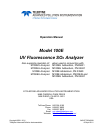
Figure 12-14: Location of UV Reference Detector Potentiometer
5. Finger tighten the thumbscrew.
NOTE
DO NOT over-tighten the thumbscrew.