Theory Of Operation Teledyne API M100E Analyzer Operation Manual
236
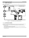
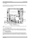
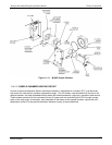
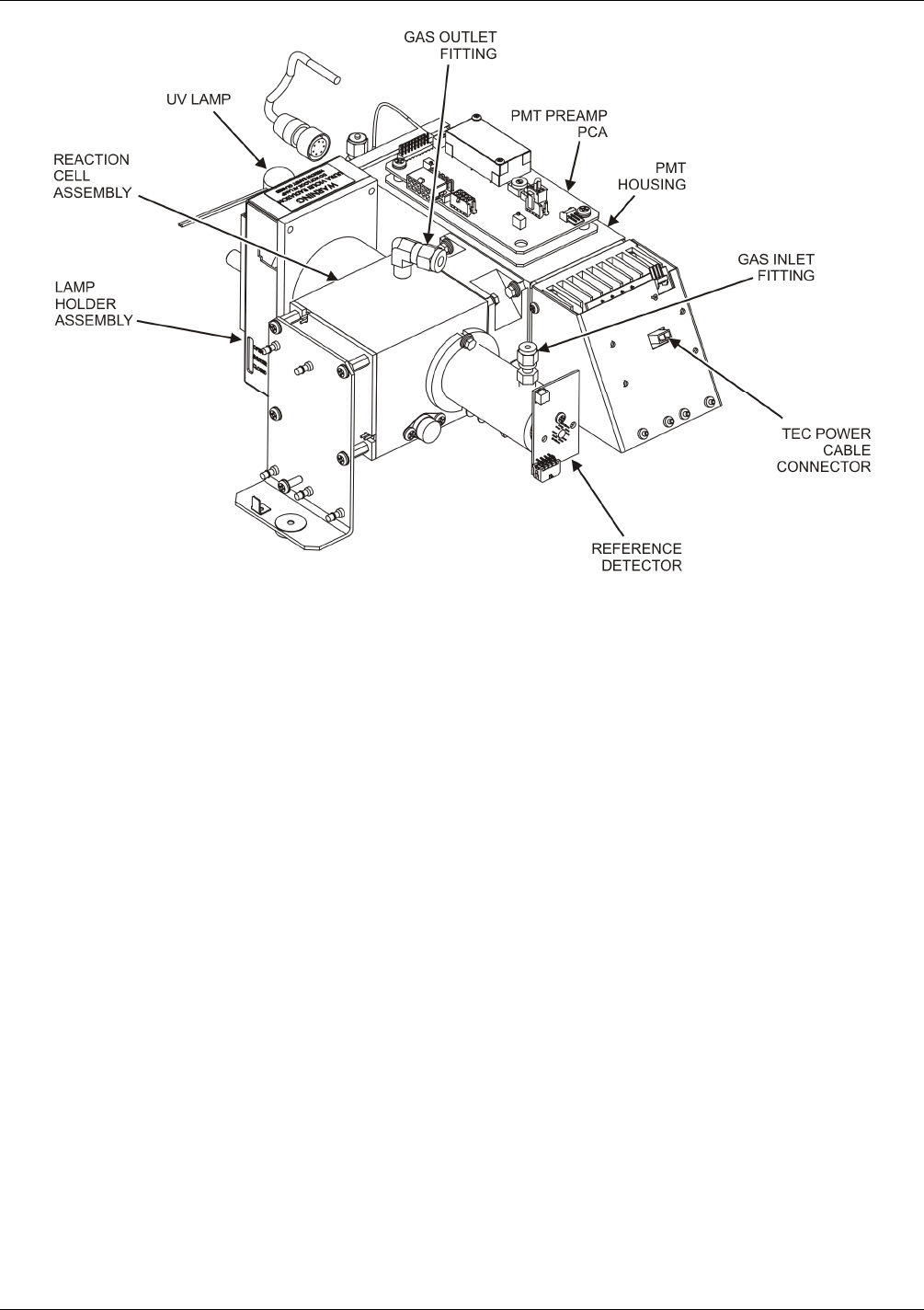
Figure 11-12: M100E Sensor Module
These components are divided into two significant subassemblies: the sample chamber and the PMT assembly.
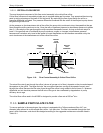
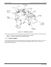
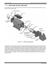
Figure 11-13 shows an exploded view of the sample chamber assembly
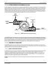
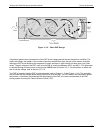
Figure 11-14 shows an exploded view of the PMT Assembly
11.4.2.1. SAMPLE CHAMBER
The main electronic components of the sample chamber are the reference detector (refer to Section 11.2.2); the
UV Lamp (refer to Section 11.2.1) and its electronically operated sh
utter (refer to Section 11.2.4); and the
sample chamber heating circuit.
04515F DCN6048


