


Troubleshooting & Repair Teledyne API M100E Analyzer Operation Manual
262
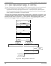
12.2.3. RELAY BOARD STATUS LEDS
The most important status LED on the relay board is the red I
2
C Bus watch-dog LED, labeled D1 (or W/D), which
indicates the health of the I
2
C communications bus. This LED is located in the upper left-hand corner of the relay
board when looking at the electronic components. If D1 is blinking, then the other LED’s can be used in
conjunction with the DIAG menu I/O functions to test hardware functionality by switching devices on and off and
watching the corresponding LED go on or off. The LED only indicates that the logic signal for an output has
been activated. If the output driver (i.e. the relay or valve driver IC) is defective, then the LED will light up, but
the attached peripheral device will not turn on.
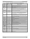
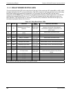
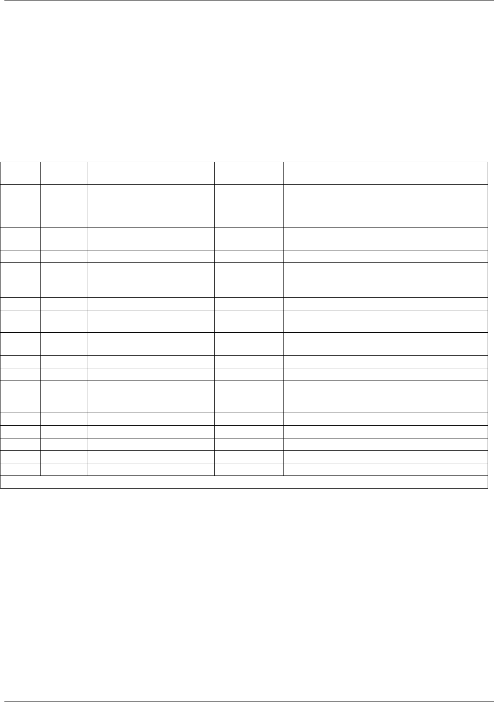
Table 12-3: Relay Board Status LEDs
LED COLOR FUNCTION
FAULT
STATUS
INDICATED FAILURE(S)
D1 red
Watchdog Circuit; I
2
C bus
operation.
Continuously
ON or OFF
Failed or halted CPU; faulty motherboard,
keyboard, relay board; wiring between
motherboard, keyboard or relay board; +5 V
power supply.
D2
yellow
Relay 0 - sample chamber
heater
Continuously
ON or OFF
Heater broken, thermistor broken
D3 yellow SPARE N/A N/A
D4
yellow SPARE N/A N/A
D5 yellow Relay 3 - IZS heater
Continuously
ON or OFF
Heater broken, thermistor broken
D6 yellow Spare N/A N/A
D7
1
green Zero/span valve status
Continuously
ON or OFF
Valve broken or stuck, valve driver chip broken
D8
1
green Sample/cal valve status
Continuously
ON or OFF
Valve broken or stuck, valve driver chip broken
D9
green SPARE N/A N/A
D10 green SPARE N/A N/A
D11 green UV Lamp Shutter
Continuously
ON or OFF
Shutter jammed or stuck; faulty relay board;
problem with wiring between relay board &
shutter.
D12 green SPARE N/A N/A
D13 green SPARE N/A N/A
D14 green SPARE N/A N/A
D15 green SPARE N/A N/A
D16 Green SPARE N/A N/A
1
Only active for instruments with Z/S valve or IZS options installed
04515F DCN6048