


Teledyne API M100E Analyzer Operation Manual Theory Of Operation
235
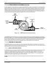
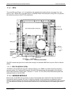
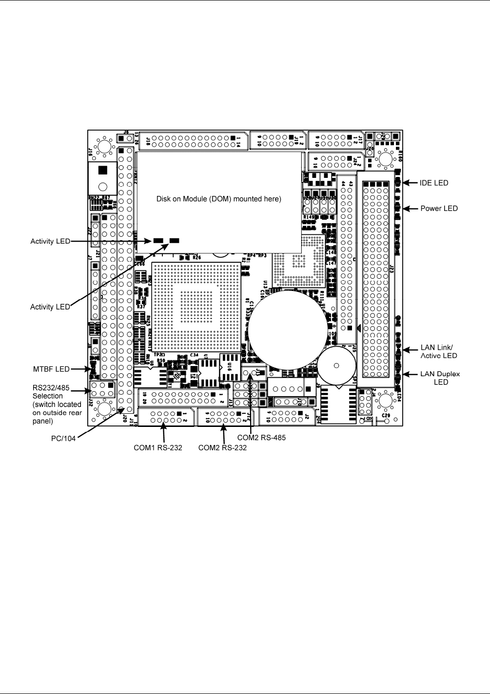
11.4.1. CPU
The unit’s CPU card (Figure 11-11) is installed on the motherboard located inside the rear panel. It is a low
power (5 VDC, 360mA max), high perfo
rmance, Vortex86SX-based microcomputer-running DOS. Its operation
and assembly conform to the PC-104 specification.
Figure 11-11: CPU Board Annotated
The CPU includes two types of non-volatile data storage: an embedded 2MB flash chip and a Disk on Module
(DOM).
11.4.1.1. DISK ON MODULE (DOM)
The DOM is a 44-pin IDE flash chip with a storage capacity up to 128MB. It is used to store the computer’s
operating system, the Teledyne API firmware, and most of the operational data generated by the analyzer’s
internal data acquisition system (iDAS - Sections 11.7.4 and 7.2). The LEDs on the DOM indicate power and
readi
ng/writin
g to or from the DOM.
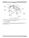
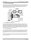
11.4.2. SENSOR MODULE
Electronically, the M100E sensor module is a group of components that: create the UV light that initiates the
fluorescence reaction between SO
2
and O
3
; sense the intensity of that fluorescence and generate various
electronic signals needed by the analyzer to determine the SO
2
concentration of the sample gas (refer to Section
11.1) and sense and control key environmental conditions su
ch as the temperature of the sample gas and the
PMT.
04515F DCN6048