


Model GFC7000E Instruction Manual Operating Instructions
04584 Rev A1 84
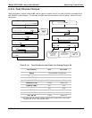
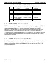
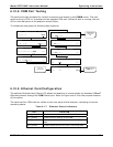
6.10.3. COMM Port Cable Connections
There are two DB-9 connectors on the MGFC7000E rear panel. COM1 is a male connector, COM2
a female connector (Table 6-15 lists pin assignments). Teledyne Instruments offers two mating
cables, one of which should be applicable for your use.
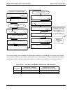
Part number WR000077, a DB-9 female to DB-9 female cable, 6 feet long, allows connection of
COM1 with the serial port of most personal computers. Also available as Option 60 (Section
5.5.1).
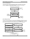
Part number WR0000024, a DB-9 female to DB-25 male cable. Allows connection to the most
common styles of modems (e.g. Hayes-compatible) and code activated switches.
Both cables are configured with straight-through wiring and should require no additional adapters.
To assist in properly connecting the serial ports to either a computer or a modem, there are
activity indicators just above each COM port. When power is applied to the analyzer, the red LED
should be illuminated. If this LED is dark, it indicates a communications error between serial port
and CPU.
Once a cable is connected between the analyzer and a computer or modem, both the red and
green LEDs should be on. If not, COM1 can be switched between DTE and DCE modes using a
small switch on the rear panel to exchange the receive and transmit lines (emulating a cross-over
or null-modem cable). If both LEDs are still not illuminated, check the cable for proper wiring. For
COM2 it may be necessary to install a null-modem cable (contact customer service for
information).
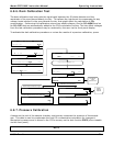
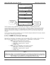
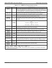
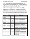
6.10.4. RS-485 Configuration of COM2
As delivered from the factory, COM2 is configured for RS-232 communications. This port can be
re-configured for operation as a non-isolated, half-duplex RS-485 port with a 150 Ω termination
resistor (Table 6-15 shows the pin assignments of the DB-9 connector).
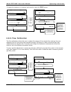
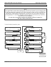
For RS-485 operation, jumper JP3 on the CPU board should be installed and switch 6 of SW1
should be set to the ON position. For RS-232, remove the jumper and set the switch to OFF
(default). JP3 is just to the right of the third connector from the left on the top of the CPU board
(as seen from the inside of the analyzer). SW1 is in the middle of the CPU board between disk-on-
chip and BIOS. For non-terminated RS-485 operation, remove the jumper on JP3 but leave switch
6 in the ON position. Refer to Figure 3-11 to locate the CPU board.