


Model GFC7000E Instruction Manual TROUBLESHOOTING & REPAIR PROCEDURES
04584 Rev A1 190
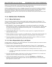
because it may be possible to recover operation of the analyzer. If after 30 – 60 seconds neither
the DS5 is flashing or no characters have been written to the front panel display then the CPU is
bad and must be replaced.
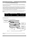
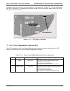
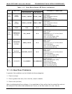
Mother Board
P/N 04069
CPU Status LED
Figure 11-3: CPU Status Indicator
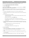
11.1.4.2. Sync Demodulator Status LED’s
Two LED’s located on the Sync/Demod Board and are there to make it obvious that the GFC
Wheel is spinning and the synchronization signals are present:
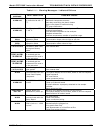
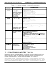
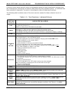
Table 11-3: Sync/Demod Board Status Failure Indications
LED Function Fault Status Indicated Failure(s)
D1 M/R Sensor
Status
LED is stuck
ON or OFF
GFC Wheel is not turning
M/R Sensor on Opto-Pickup Board failed
Sync/Demod Board failed
JP 4 Connector/Wiring faulty
Failed/Faulty +5 VDC Power Supply (PS1)
D2 Segment
Sensor Status
LED is stuck
ON or OFF
GFC Wheel is not turning
Segment Sensor on Opto-Pickup Board failed
Sync/Demod Board failed
JP 4 Connector/Wiring faulty
Failed/Faulty +5 VDC Power Supply (PS1)