


Model GFC7000E Instruction Manual Operating Instructions
04584 Rev A1 75
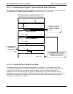
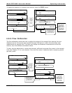
6.9.4.4. Current Loop Output Adjustment
A current loop option is available and can be installed as a retrofit for each of the analog outputs
of the analyzer (Sections 5.2). This option converts the DC voltage analog output to a current
signal with 0-20 mA output current. The outputs can be scaled to any set of limits within that 0-20
mA range. However, most current loop applications call for either 2-20 mA or 4-20 mA range. All
current loop outputs have a +5% over-range. Ranges with the lower limit set to more than 1 mA
(e.g., 2-20 or 4-20 mA) also have a -5% under-range.
To switch an analog output from voltage to current loop after installing the current output printed
circuit assembly, follow the instructions in Section 6.9.4.4 and select CURR from the list of
options on the RANGE menu.
Adjusting the signal zero and span values of the current loop output is done by raising or lowering
the voltage of the respective analog output. This proportionally raises or lowers the current
produced by the current loop option.
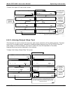
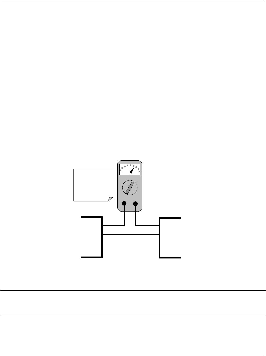
Similar to the voltage calibration, the software allows this current adjustment to be made in 100,
10 or 1 count increments. Since the exact current increment per voltage count varies from output
to output and from instrument to instrument, you will need to measure the change in the current
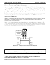
with a current meter placed in series with the output circuit (Figure 6-6).
mA
IN OUT
V OUT +
V OUT -
I IN +
I IN -
Recording
Device
Analyzer
See Table 3-2 for
pin assignments o
f
the Analog Out
connector on the
rear panel.
Figure 6-6: Setup for Calibrating Current Outputs
NOTE
Do not exceed 60 V between current loop outputs and instrument ground.
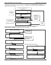
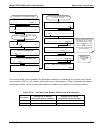
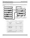
To adjust the zero and span values of the current outputs, activate the ANALOG I/O
CONFIGURATION MENU (see Section 6.9.1), then press: