


Model GFC7000E Instruction Manual TROUBLESHOOTING & REPAIR PROCEDURES
04584 Rev A1 189
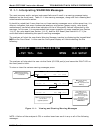
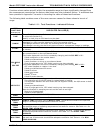
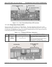
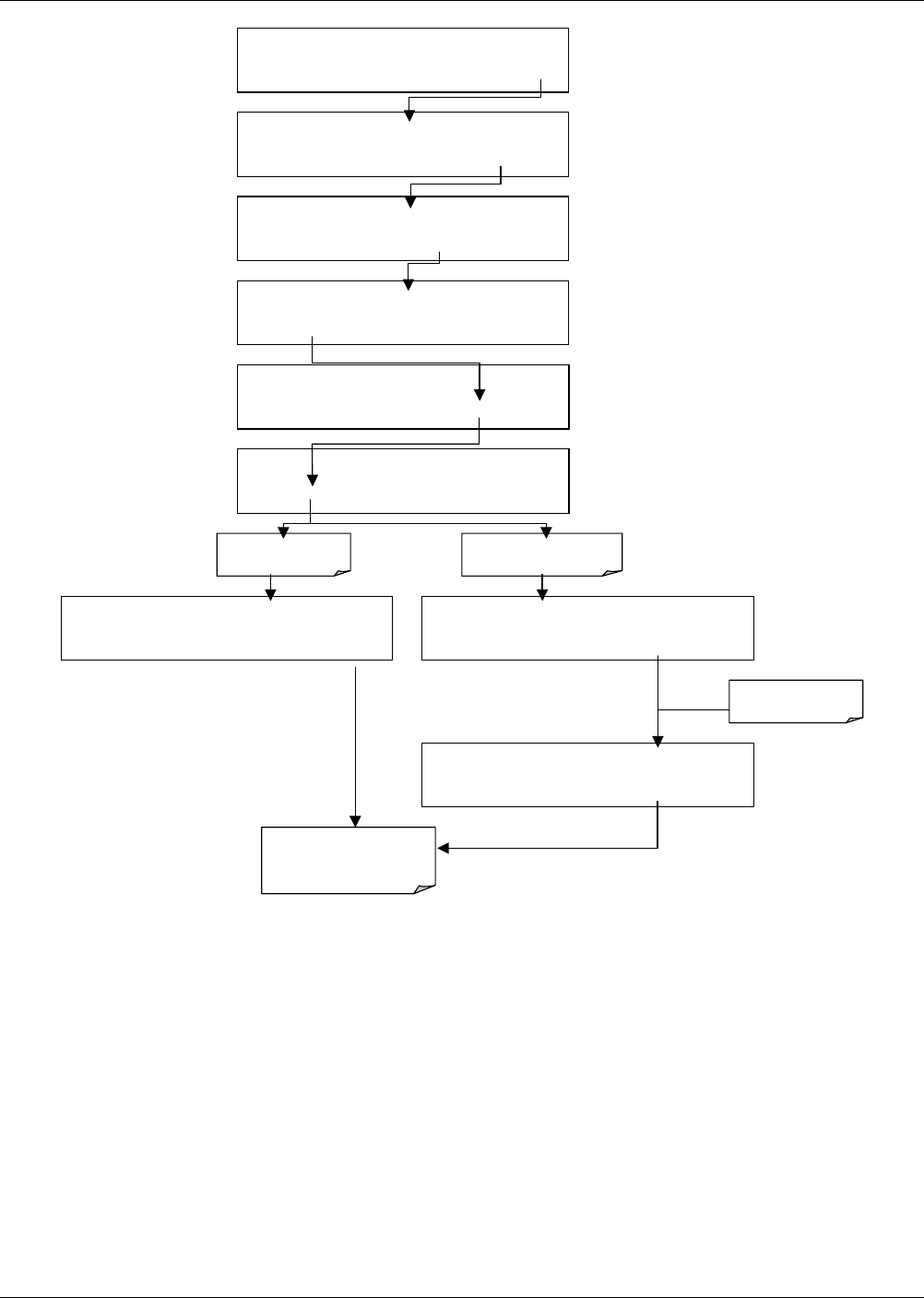
Toggles parameter
ON/OFF
Exit returns to
DIAG display & all values
return to software control
DIAG SIGNAL I/O
PREV NEXT ENTR EXIT
DIAG I/O 0 ) EXT_ZERO_CAL=ON
PREV NEXT JUMP PRNT EXIT
DIAG I/O 22) WHEEL_HTR=ON
PREV NEXT JUMP
ON
PRNT EXIT
DIAG I/O 28) SAMPLE_PRESSURE=2540 MV
PREV NEXT JUMP PRNT EXIT
DIAG I/O 22
)
WHEEL_HTR=
OFF
PREV NEXT JUMP OFF PRNT EXIT
If parameter is an
input signal
If parameter is an output
signal or control
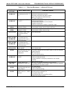
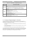
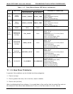
SETUP X.X
SECONDARY SETUP MENU
COMM VARS DIAG EXIT
SAMPLE ENTER SETUP PASS : 818
8 1 8 ENTR EXIT
SETUP X.X
PRIMARY SETUP MENU
CFG DAS RNGE PASS CLK MORE EXIT
SAMPLE* RANGE = 500.000 PPM CO2 =X.XXX
< TST TST > CAL SETUP
Figure 11-2: Example of Signal I/O Function
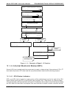
11.1.4. Internal Electronic Status LED’s
Several LED’s are located inside the instrument to assist in determining if the analyzer’s CPU, I
2
C
buss and relay board, GFC wheel and the sync/demodulator board are functioning properly.
11.1.4.1. CPU Status Indicator
DS5, a red LED, that is located on upper portion of the motherboard, just to the right of the CPU
board, flashes when the CPU is running the main program loop. After power-up, approximately
30 to 60 seconds, DS5 should flash on and off. If characters are written to the front panel display
but DS5 does not flash then the program files have become corrupted, contact customer service