


Model GFC7000E Instruction Manual TROUBLESHOOTING & REPAIR PROCEDURES
04584 Rev A1 200
11.4.2. DC Power Supply
If you have determined that the analyzer’s AC mains power is working, but the unit is still not
operating properly, there may be a problem with one of the instrument’s switching power
supplies. The supplies can have two faults, namely no DC output, and noisy output.
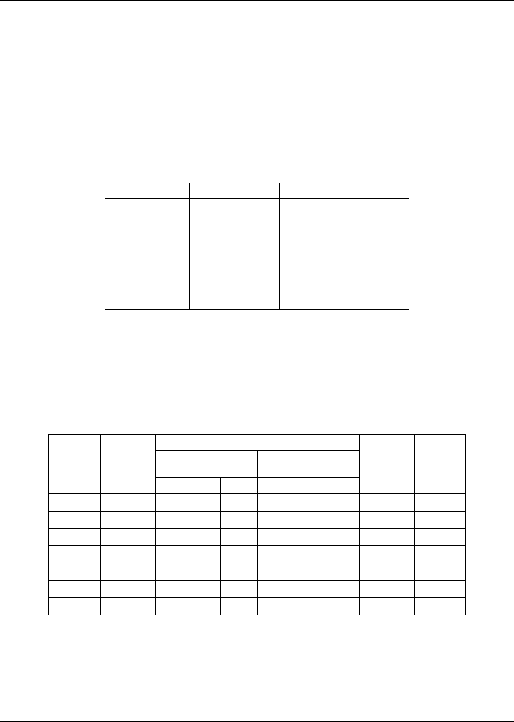
To assist tracing DC Power Supply problems, the wiring used to connect the various printed circuit
assemblies and DC Powered components and the associated test points on the relay board follow
a standard color-coding scheme as defined in Table.
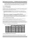
Table 11-6: DC Power Test Point and Wiring Color Codes
NAME TEST POINT# TP AND WIRE COLOR
Dgnd 1 Black
+5V 2 Red
Agnd 3 Green
+15V 4 Blue
-15V 5 Yellow
+12V 6 Purple
+12R 7 Orange
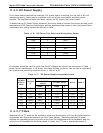
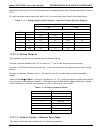
A voltmeter should be used to verify that the DC voltages are correct per the values in Table
below, and an oscilloscope, in AC mode, with band limiting turned on, can be used to evaluate if
the supplies are producing excessive noise (> 100 mV p-p).
Table 11-7: DC Power Supply Acceptable Levels
CHECK RELAY BOARD TEST POINTS
FROM TEST
POINT
TO TEST POINT
POWER
SUPPLY
ASSY
VOLTAG
E
NAME # NAME #
MIN V MAX V
PS1 +5 Dgnd 1 +5 2 4.8 5.25
PS1 +15 Agnd 3 +15 4 13.5 16V
PS1 -15 Agnd 3 -15V 5 -14V -16V
PS1 Agnd Agnd 3 Dgnd 1 -0.05 0.05
PS1 Chassis Dgnd 1 Chassis N/A -0.05 0.05
PS2 +12 +12V Ret 6 +12V 7 11.75 12.5
PS2 Dgnd +12V Ret 6 Dgnd 1 -0.05 0.05
11.4.3. I
2
C Bus
Operation of the I
2
C buss can be verified by observing the behavior of D1 on the Relay Board in
conjunction with the performance of the front panel display. Assuming that the DC power
supplies are operating properly and the wiring from the Motherboard to the Keyboard, and the
wiring from the keyboard to the Relay board, is intact, the I
2
C buss is operating properly if: