


Model GFC7000E Instruction Manual TROUBLESHOOTING & REPAIR PROCEDURES
04584 Rev A1 201
• D1 on the relay board is flashing, or
• D1 is not flashing but pressing a key on the front panel results in a change to the display.
11.4.4. Keyboard/Display Interface
The front panel keyboard, display and Keyboard Display Interface PCA (03975 or 04258) can be
verified by observing the operation of the display when power is applied to the instrument and
when a key is pressed on the front panel. Assuming that there are no wiring problems and that
the DC power supplies are operating properly:
1. The vacuum fluorescent display is good if on power-up a “-“ character is visible on the upper
left hand corner of the display.
2. The CPU Status LED, DS5, is flashing, see Section 11.1.4.1.
3. If there is a “-“ character on the display at power-up and D1 on the relay board is flashing
then the keyboard/display interface PCA is bad.
4. If the analyzer starts operation with a normal display but pressing a key on the front panel
does not change the display, then there are three possible problems:
• One or more of the keys is bad,
• The interrupt signal between the Keyboard Display interface and the motherboard is
broken, or
• The Keyboard Display Interface PCA is bad.
11.4.5. Relay Board
The relay board PCA (04135) can be most easily checked by observing the condition of the its
status LEDs on the relay board, as described in Section 11.1.4.3, and the associated output when
toggled on and off through signal I/O function in the diagnostic menu, see Section 11.1.3.
1. If the front panel display responds to key presses and D1 on the relay board is NOT flashing
then either the wiring between the Keyboard and the relay board is bad, or the relay board is
bad.
2. If D1 on the relay board is flashing and the status indicator for the output in question (heater
power, valve drive, etc.) toggles properly using the signal I/O function, then the associated
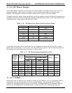
control device on the relay board is bad. Several of the control devices are in sockets and can
be easily replaced. The table below lists the control device associated with a particular
function:
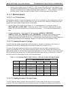
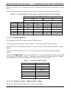
Table 11-8: Relay Board Control Devices
FUNCTION
CONTROL
DEVICE
IN SOCKET
Wheel Heater K1 Yes
Bench Heater K2 Yes
Spare AC Control K3 Yes
IZS Valves U4 Yes