Model GFC7000E Instruction Manual THEORY OF OPERATION
04584 Rev A1 157
calibration SLOPE and OFFSET values to produce the CO
2
concentration which is then normalized
for changes in sample pressure.
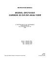
IR shining through both cells is
effected equally by interfering gas
in the Sample Chamber
M/R
is Shifted
Figure 10-5: Effects of Interfering Gas on CO2 MEAS & CO2 REF
If an interfering gas, such as H
2
O vapor is introduced into the sample chamber, the spectrum of
the IR beam is changed in a way that is identical for both the reference and the measurement
cells, but without changing the ratio between the peak heights of CO
2
MEAS and CO
2
REF. In
effect, the difference between the peak heights remains the same.
Thus, the difference in the peak heights and the resulting M/R ratio is only due to CO
2
and not to
interfering gases. In this way, Gas filter correlation rejects the effects of interfering gases and so
that the analyzer responds only to the presence of CO
2
.
To improve the signal-to-noise performance of the IR photo-detector, the GFC wheel also
incorporates an optical mask that chops the IR beam into alternating pulses of light and dark at
six times the frequency of the measure/reference signal. This limits the detection bandwidth
helping to reject interfering signals from outside this bandwidth improving the signal to noise
ration.
The IR Signal as the Photo-Detector
sees it after bein
chopped by the GFC
Wheel Screen
CO REF
CO
MEAS
Figure 10-6: Chopped IR Signal