Model GFC7000E Instruction Manual Operating Instructions
04584 Rev A1 83
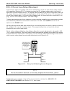
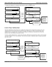
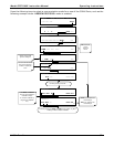
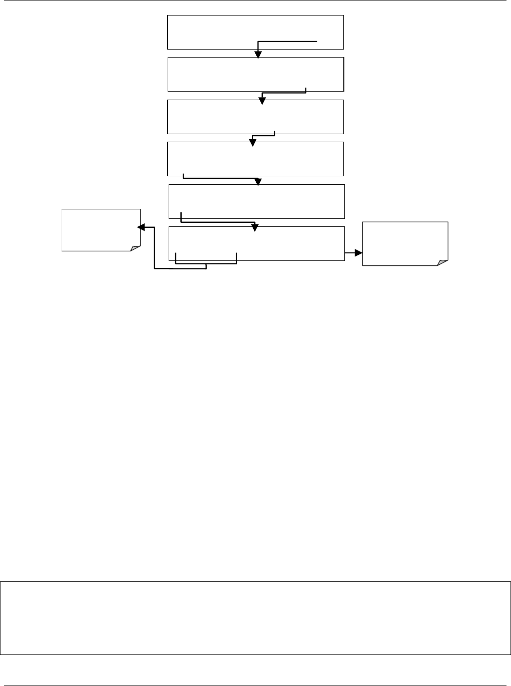
SETUP X.X COMMUNICATIONS MENU
ID COM1 COM2 EXIT
SETUP X. MACHINE ID: 360 ID
0 3 6 0 ENTR EXIT
SETUP X.X PRIMARY SETUP MENU
CFG DAS RNGE PASS CLK MORE EXIT
SETUP X.X SECONDARY SETUP MENU
COMM VARS DIAG ALRM EXIT
SAMPLE* RANGE = 500.000 PPM CO2 =X.XXX
< TST TST > CAL SETUP
SAMPLE
ENTER SETUP PASS : 818
8 1 8 ENTR EXIT
Toggle these keys to
cycle through the
available character set:
0-9
ENTR key accepts the
new settings
EXIT key ignores the
new settin
g
s
The ID number is only important if more than one analyzer is connected to the same
communications channel (e.g., a multi-drop setup). Different models of Teledyne Instruments
analyzers have different default ID numbers, but if two analyzers of the same model type are
used on one channel (for example, two MGFC7000E’s), the ID of one instrument needs to be
changed.
The ID can also be used for to identify any one of several analyzers attached to the same network
but situated in different physical locations.
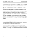
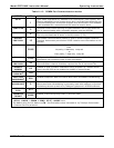
6.10.2. COMM Port Default Settings
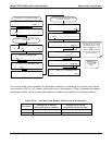
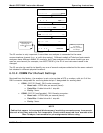
Received from the factory, the analyzer is set up to emulate a DCE or modem, with pin 3 of the
DB-9 connector designated for receiving data and pin 2 designated for sending data.
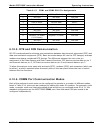
• COM1: RS-232 (fixed), DB-9 male connector.
o Baud rate: 19200 bits per second (baud).
o Data Bits: 8 data bits with 1 stop bit.
o Parity: None.
• COM2: RS-232 (configurable), DB-9 female connector.
o Baud rate: 115000 bits per second (baud).
o Data Bits: 8 data bits with 1 stop bit.
o Parity: None.
NOTE
Cables that appear to be compatible because of matching connectors may incorporate
internal wiring that make the link inoperable. Check cables acquired from sources other
than Teledyne Instruments for pin assignments before using.


