


Model GFC7000E Instruction Manual Getting Started
04584 Rev A1 13
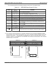
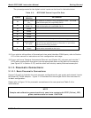
Table 3-1: GFC7000E Analog Output Pin Outs
Pin Analog Output VDC Signal mADC Signal
1 V Out I Out +
2
A1
Ground I Out -
3 V Out I Out +
4
A2
Ground I Out -
5 V Out I Out +
6
A3
Ground I Out -
7 V Out Not Available
8
A4 (Spare)
Ground Not Available
• The default analog output voltage setting of the GFC7000E CO
2
Analyzer is 0 – 5 VDC
with a range of 0 – 500 ppm.
• TO change these settings, see Sections 6.9.4 and 6.7 respectively.
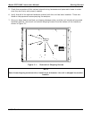
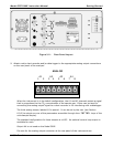
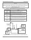
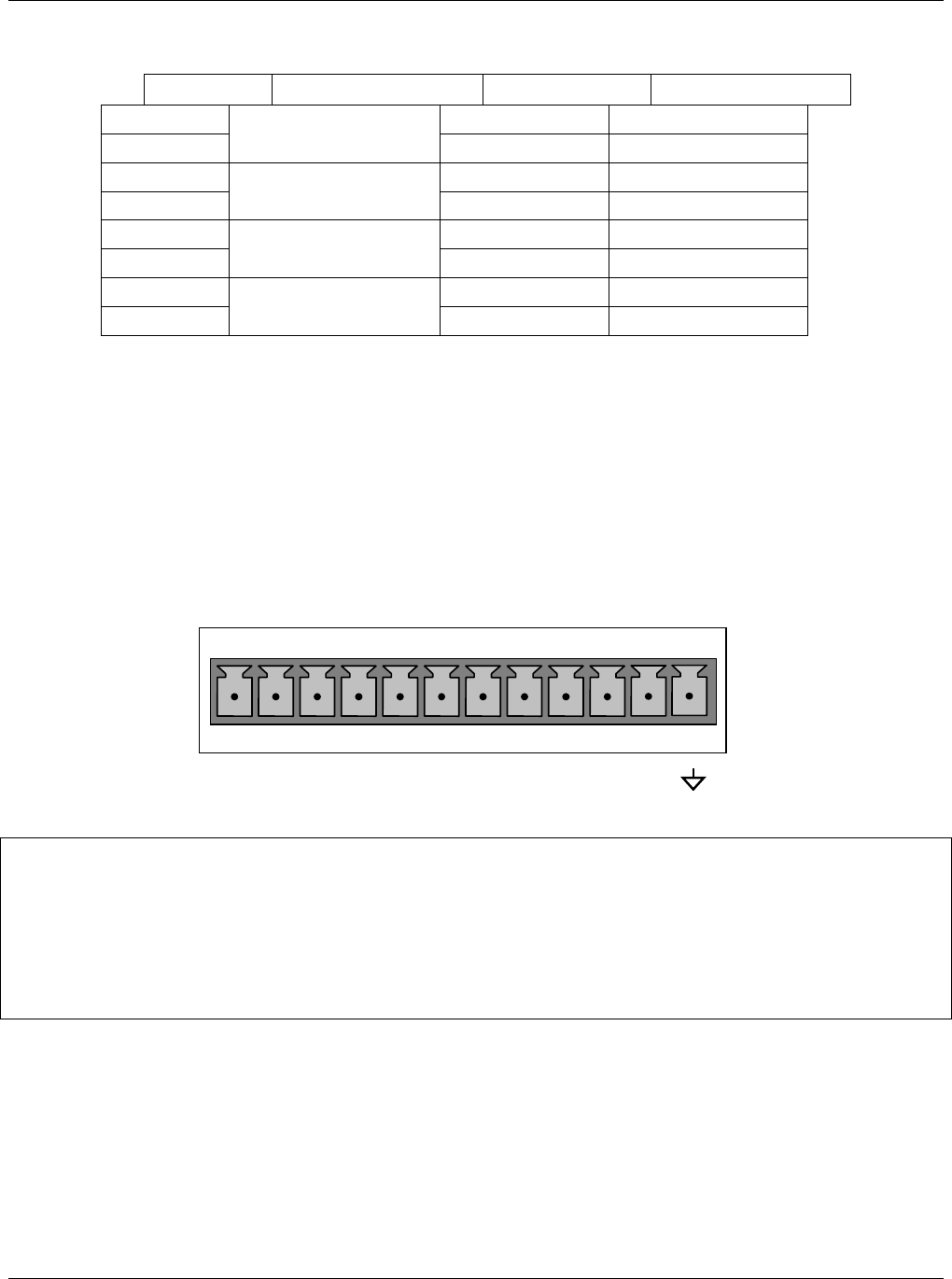
10. If you wish utilize the analyzer’s status outputs to interface with a device that accepts logic-
level digital inputs, such as programmable logic controllers (PLC’s) they are accessed via a 12-
pin connector on the analyzer’s rear panel labeled STATUS.
STATUS
1 2 3 4 5 6 7 8 D
+
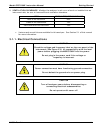
NOTE
Most PLC’s have internal provisions for limiting the current that the input will draw from
an external device. When connecting to a unit that does not have this feature, an
external dropping resistor must be used to limit the current through the transistor
output to less than 50mA. At 50mA, the transistor will drop approximately 1.2V from its
collector to emitter.