


Model GFC7000E Instruction Manual THEORY OF OPERATION
04584 Rev A1 160
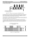
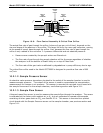
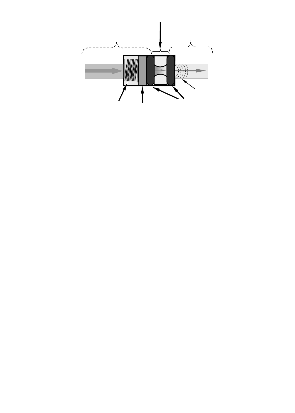
SPRING
O-RINGS
FILTER
CRITICAL
FLOW
ORIFICE
A
REA OF
LOW
PRESSURE
AREA OF
HIGH
PRESSURE
Sonic
Shockwave
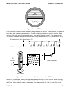
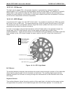
Figure 10-8: Flow Control Assembly & Critical Flow Orifice
The actual flow rate of gas through the orifice (volume of gas per unit of time), depends on the
size and shape of the aperture in the orifice. The larger the hole, the more gas molecules, moving
at the speed of sound, pass through the orifice. Also, because the flow rate of gas through the
orifice is only related to the minimum 2:1 pressure differential and not absolute pressure:
• Pressure wave created by the pump’s action are filtered out.
• The flow rate of gas through the sample chamber will be the same regardless of whether
the analyzer is at the bottom of Death Valley or on top of Pikes Peak.
• The flow rate of the gas is also unaffected by degradations in pump efficiency due to age.
The critical flow orifice used in the Model GFC7000E is designed to provide a flow rate of 800
cm
3
/min.
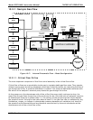
10.2.1.2. Sample Pressure Sensor
An absolute value pressure transducer plumbed to the outlet of the sample chamber is used to
measure sample pressure. The output of the sensor is used to compensate the concentration
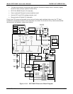
measurement for changes in air pressure. This sensor is mounted to a printed circuit board with
the sample flow sensor on the sample chamber; see following section and Figure 3-11.
10.2.1.3. Sample Flow Sensor
A thermal-mass flow sensor is used to measure the sample flow through the analyzer. The sensor
is calibrated at the factory with ambient air or N
2
, but can calibrated to operate with samples
consisting of other gases such as CO
2
, see Section 9.3.4. This sensor is mounted to a printed
circuit board with the Sample Pressure sensor on the sample chamber; see previous section and
Figure 3-11.