Model GFC7000E Instruction Manual Operating Instructions
04584 Rev A1 89
6.10.8. COM Port Testing
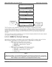
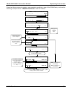
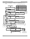
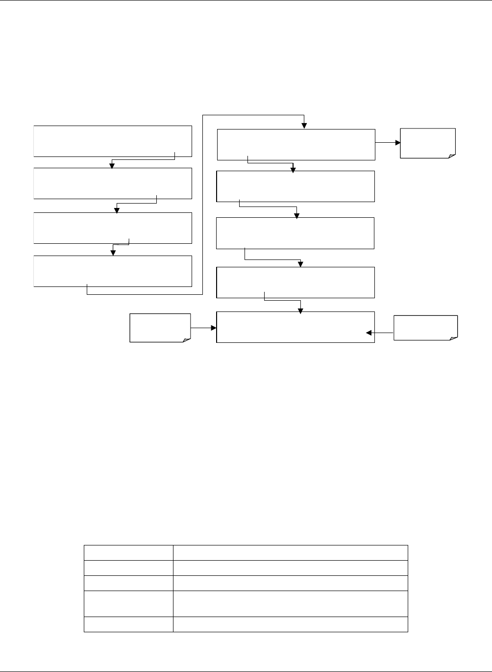
The serial ports can be tested for correct connection and output in the COMM menu. This test
sends a string of 256 ‘w’ characters to the selected COM port. While the test is running, the red
LED on the rear panel of the analyzer should flicker.
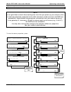
To initiate the test press the following key sequence.
SAMPLE RANGE = 500.000 PPM CO2 =X.XXX
< TST TST > CAL
SETUP
SAMPLE
ENTER SETUP PASS : 818
8 1 8
ENTR
EXIT
SETUP X.X
PRIMARY SETUP MENU
CFG DAS RNGE PASS CLK
MORE
EXIT
SETUP X.X
SECONDARY SETUP MENU
COMM VARS
DIAG
ALRM EXIT
Select which
COM port to
test.
SETUP X.X
COMMUNICATIONS MENU
ID
COM1
COM2
EXIT
SETUP X.X
COM1 : TEST PORT
<SET
TEST
EXIT
SETUP X.X
TRANSMITTING TO COM1
<SET
TEST
EXIT
SETUP X.X
COM1 MODE:0
SET>
EDIT EXIT
SETUP X.X COM1 BAUD RATE:19200
<SET
SET>
EDIT
EXIT
EXIT returns to
COMM menu
Test runs
automatically
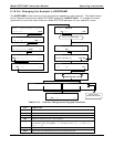
6.10.9. Ethernet Card Configuration
The optional Ethernet card (Option 63) allows the analyzer to communicate via standard 10BaseT
Ethernet protocol through the COM2 serial port. Refer to Figure and 5-4 for the physical location
of this option.
The card has four LEDs that are visible on the rear panel of the analyzer, indicating its current
operating status.
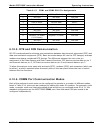
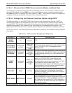
Table 6-17: Ethernet Status Indicators
LED FUNCTION
LNK (green) ON when connection to the LAN is valid.
ACT (yellow) Flickers on any activity on the LAN.
TxD (green) Flickers when the RS-232 port is transmitting
data.
RxD (yellow) Flickers when the RS-232 port is receiving data.


