


Model GFC7000E Instruction Manual THEORY OF OPERATION
04584 Rev A1 163
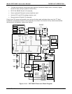
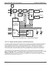
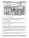
10.3.2. CPU
The Model GFC7000E’s CPU is a, low power (5 VDC, 0.8A max), high performance, 386-based
microcomputer running MS-DOS. Its operation and assembly conform to the PC/104 Specification
version 2.3 for embedded PC and PC/AT applications. It has 2 MB of DRAM on board and operates
at 40MHz over an internal 32-bit data and address bus. Chip to chip data handling is performed
by two 4-channel DMA devices over data busses of either 8-bit or 16-bit configuration. The CPU
supports both RS-232 and RS-485 serial I/O.
The CPU includes two types of non-volatile data storage.
Disk On Chip
While technically an EEPROM, the Disk –on-Chip (DOC), this device appears to the CPU as,
behaves as, and performs the same function in the system as an 8MB disk drive. It is used to
store the operating system for the computer, the Teledyne Instruments Firmware, and most of
the operational data generated by the analyzer’s internal data acquisition system (iDAS - see
Section 6.12).
Flash Chip
Another, smaller EEPROM used to store critical calibration and configuration data. Segregating
this data on a separate, less heavily accessed chip significantly decreases the chance of this key
data being corrupted.
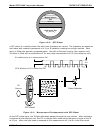
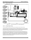
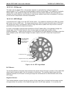
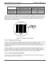
10.3.3. Optical Bench & GFC Wheel
Electronically, the Model GFC7000E’s optical bench, GFC wheel and associated components do
more than simply measure the amount of CO
2
present in the sample chamber. A variety of other
critical functions are performed here as well.
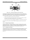
10.3.3.1. Sample Gas and GFC Temperature Control
Because the temperature of a gas affects its density and therefore the amount of light absorbed
by that gas it is important to reduce the effect of fluctuations in ambient temperature on the
Model GFC7000E’s measurement of CO
2
. To accomplish this both the temperature of the sample
chamber and the GFC Wheel are maintained at constant temperatures above their normal
operating ranges.
Bench Temperature
: To minimize the effects of ambient temperature variations on the sample
measurement, the sample chamber is heated to 48°C (8 degrees above the maximum suggested
ambient operating temperature for the analyzer). A strip heater attached to the underside of the
chamber housing is the heat source. The temperature of the sample chamber is sensed by a
thermistor, also attached to the sample chamber housing.
Wheel Temperature
: To minimize the effects of temperature variations caused by the near
proximity of the IR Source to the GFC wheel on the gases contained in the wheel, it is also raised
to a high temperature level. Because the IR Source itself is very hot, the set point for this heat
circuit is 68°C. A cartridge heater is implanted into the heat sync on the motor is the heat source.
The temperature of the wheel/motor assembly is sensed by a thermistor also inserted into the
heat sync.
Both heaters operate off of the AC line voltage supplied to the instrument.