


Model GFC7000E Instruction Manual THEORY OF OPERATION
04584 Rev A1 162
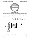
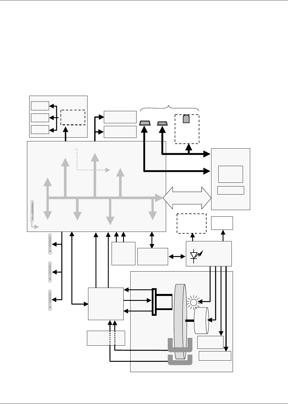
• Through the analyzer’s keyboard and vacuum florescent display over a clocked, digital,
serial I/O bus (using a protocol called I2C);
• RS 232 & RS485 Serial I/O channels;
• Via an optional Ethernet communications card:
• Various DCV and DCA analog outputs, and
• Several sets of Digital I/O channels.
Finally, the CPU issues commands via a series of relays and switches (also over the I
2
C bus)
located on a separate printed circuit assembly to control the function of key electromechanical
devices such as heaters, motors and valves.
Analog Outputs
Sample
Flow &
Pressure
Sensors
Status Outputs:
1 – 8
Control Inputs:
1 – 8
PC 104
CPU Card
Disk On
Chip
Flash Chip
RS–232
or RS-485
RS –
232
Power-Up
Circuit
Internal
Digital I/O
I
2
C
Bus
Sensor Inputs
Box
Temp
Thermistor
Interface
SAMPLE
TEMP
BENCH
TEMP
WHEEL
TEMP
A1
A2
A3
Optional
4-20 mA
MOTHER
BOARD
A/D
Converter
(V/F)
PC 104 Bus
External
Digital I/O)
B
ac
k P
ane
l
Connectors
Analog
Outputs
(D/A)
T
EC Control
PHT
Drive
Detector
Output
Segment Sensor
M / R Senso
r
GFC
Wheel
GFC
Motor
Zero/Span
Valve
Options
Wheel
Heater
Bench Heater
Keyboard
&
Display
Sensor
Status
&
Control
Optical
Bench
RELAY
BOARD
IR
Source
Photo-
detector
SYNC
DEMOD
C
O
2
M
E
A
S
C
O
2
R
E
F
CPU Status
LED
Schmidt
Trigger
PUMP
COM-A COM-B
Optional
Ethernet
Interface
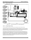
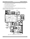
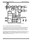
Figure 10-9: GFC7000E Electronic Block Diagram