Model GFC7000E Instruction Manual TROUBLESHOOTING & REPAIR PROCEDURES
04584 Rev A1 208
please use the following procedure (see the Spare Parts list in Appendix B for part numbers and
kits):
1. Turn off power to the analyzer.
2. Locate the assembly attached to the sample pump, see Figure 3–11.
3. Disconnect the pneumatic connection from the flow assembly and the assembly from the
pump.
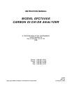
4. Remove the fitting and the components as shown in the exploded view in Figure 11.6.
5. Replace the o-rings (p/n:OR_01) and the sintered filter (p/n:FL_01).
6. If replacing the critical flow orifice itself (p/n:00094100), make sure that the side with the
colored window (usually red) is facing upstream to the flow gas flow.
7. Re-assemble in reverse order.
8. After reconnecting the power and pneumatic lines, flow check the instrument as described in
the Section 9.3.4.
Pneumatic Connector, Male 1/8”
P/N FT
70
Spring
P/N HW
20
Sintered Filter
P/N FL
01
Critical Flow Orifice
P/N 00094100
O-Ring
P/N OR
01
Purge Housing
P/N 000850000
Figure 11-6: Critical Flow Restrictor Assembly Disassembly