


Model GFC7000E Instruction Manual Calibration Procedures
04584 Rev A1 142
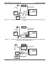
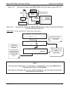
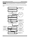
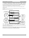
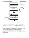
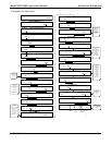
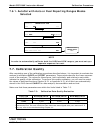
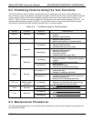
7.6.1. AutoCal with Auto or Dual Reporting Ranges Modes
Selected
SETUP C.4 RANGE TO CAL: HIGH
<SET EDIT EXIT
EXIT
returns to the
PRIMARY SETUP
Menu
SETUP C.4
SEQ 2) ZERO
–
SPAN, 2:00:30
PREV NEXT MODE SET
EXIT
SETUP C.4
RANGE TO CAL: LOW
LOW HIGH ENTR SETUP
SETUP C.4 RANGE TO CAL: LOW
<SET EDIT EXIT
NOTE
In order to automatically calibrate both the HIGH and LOW ranges, you must set up a
separate sequence for each.
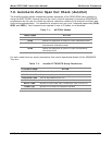
7.7. Calibration Quality
After completing one of the calibration procedures described above, it is important to evaluate the
analyzer’s calibration SLOPE and OFFSET parameters. These values describe the linear response
curve of the analyzer. The values for these terms, both individually and relative to each other,
indicate the quality of the calibration. To perform this quality evaluation, you will need to record
the values of both test functions (Section 6.2.1 or Appendix A-3), all of which are automatically
stored in the iDAS channel CALDAT for data analysis, documentation and archival.
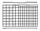
Make sure that these parameters are within the limits listed in Table 7-3.
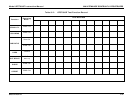
Table 7-3: Calibration Data Quality Evaluation
FUNCTION MINIMUM VALUE OPTIMUM VALUE MAXIMUM VALUE
SLOPE 0.700 1.000 1.300
OFFS -0.500 0.000 0.500
These values should not be significantly different from the values recorded on the Teledyne
Instruments Final Test and Validation Data sheet that was shipped with your instrument. If
they are, refer to the troubleshooting Chapter 11.
User Notes