


Model GFC7000E Instruction Manual THEORY OF OPERATION
04584 Rev A1 156
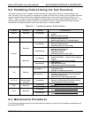
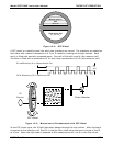
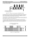
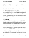
does not absorb IR light. This results in a fluctuation in the intensity of the IR light striking the
photo-detector (See Figure 10-3) that results in the output of the detector resembling a square
wave.
The Model GFC7000E determines the amount of CO
2
in the sample chamber by computing the
ratio between the peak of the measurement pulse (CO2 MEAS) and the peak of the reference
pulse (CO2 REF).
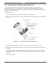
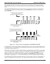
IR unaffected by N
2
in Measurement
Cell of the GDC Wheel and no
additional CO
2
in the Sample Chamber
IR affected by CO
2
in Reference
Cell with no interfering gas in the
Sample Chamber
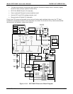
IR shinning through Measurement Cell
of the GDC Wheel is reduced by
additional CO
2
in the Sample Chamber
IR shining through Reference Cell
is also reduced by additional CO
2
in the Sample Chamber, but to a
lesser extent
M/R
is reduced
CO2 REF
CO2 MEAS
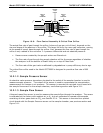
Figure 10-4: Affect of CO
2
in the Sample on CO2 MEAS & CO2 REF
If no gases exist in the sample chamber that absorb light at 4.3μm, the high concentration of CO
2
in the gas mixture of the reference cell will attenuate the intensity of the IR beam by 60% giving
a M/R ratio of approximately 2.4:1.
Adding CO
2
to the sample chamber causes the peaks corresponding to both cells to be attenuated
by a further percentage. Since the intensity of the light passing through the measurement cell is
greater, the effect of this additional attenuation is greater. This causes CO2 MEAS to be more
sensitive to the presence of CO
2
in the sample chamber than CO2 REF and the ratio between
them (M/R) to move closer to 1:1 as the concentration of CO
2
in the sample chamber increases.
Once the Model GFC7000E has computed this ratio, a look-up table is used, with interpolation, to
linearize the response of the instrument. This linearized concentration value is combined with