


Model GFC7000E Instruction Manual Operating Instructions
04584 Rev A1 116
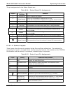
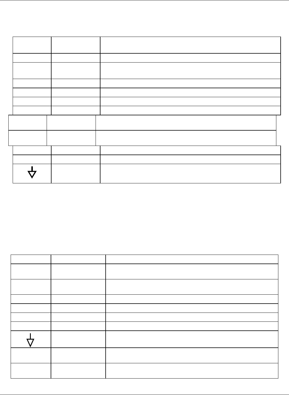
The pin assignments for the Status Outputs are:
Table 6-24: Status Output Pin Assignments
Output #
Status
Definition
Condition
1 SYSTEM OK On if no faults are present.
2
CONC VALID
On if CO
2
concentration measurement is valid.
If the CO
2
concentration measurement is invalid, this bit is OFF.
3 HIGH RANGE On if unit is in high range of DUAL or AUTO range modes.
4 ZERO CAL On whenever the instruments zero point is being calibrated.
5 SPAN CAL On whenever the instruments span point is being calibrated.
6 DIAG MODE On whenever the instrument is in diagnostic mode.
7 ALARM1
On whenever the measured CO
2
concentration is above the set
point for ALM1
8 ALARM2
On whenever the measured CO
2
concentration is above the set
point for ALM2
D EMITTER BUSS The emitters of the transistors on pins 1-8 are bussed together.
+ DC POWER + 5 VDC
Digital Ground The ground level from the analyzer’s internal DC power supplies.
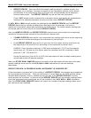
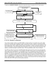
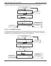
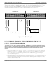
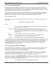
6.13.1.2. Control Inputs
These inputs allow the user to remotely initiate Zero and Span calibrations. Two methods for
energizing the inputs is provided below; the first using the internal +5V available on the CONTROL
IN connector and the second, if an external, isolated supply is employed.
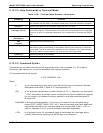
Table 6-25: Control Input Pin Assignments
Input Status Condition when enabled
A
EXTERNAL ZERO
CAL
Zero calibration mode is activated. The mode field of the
display will read ZERO CAL R.
B
EXTERNAL SPAN
CAL
Span calibration mode is activated. The mode field of the
display will read SPAN CAL R.
C Unused
D Unused
E Unused
F Unused
DIGITAL GROUND Provided to ground an external device (e.g., recorder).
U
DC power for
Input pull ups
Input for +5 VDC required to activate inputs A - F. This voltage
can be taken from an external source or from the “+” pin.
+
Internal +5V
Supply
Internal source of +5V which can be used to activate inputs
when connected to pin U.