


Model GFC7000E Instruction Manual Getting Started
04584 Rev A1 15
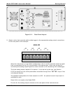
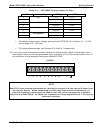
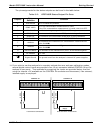
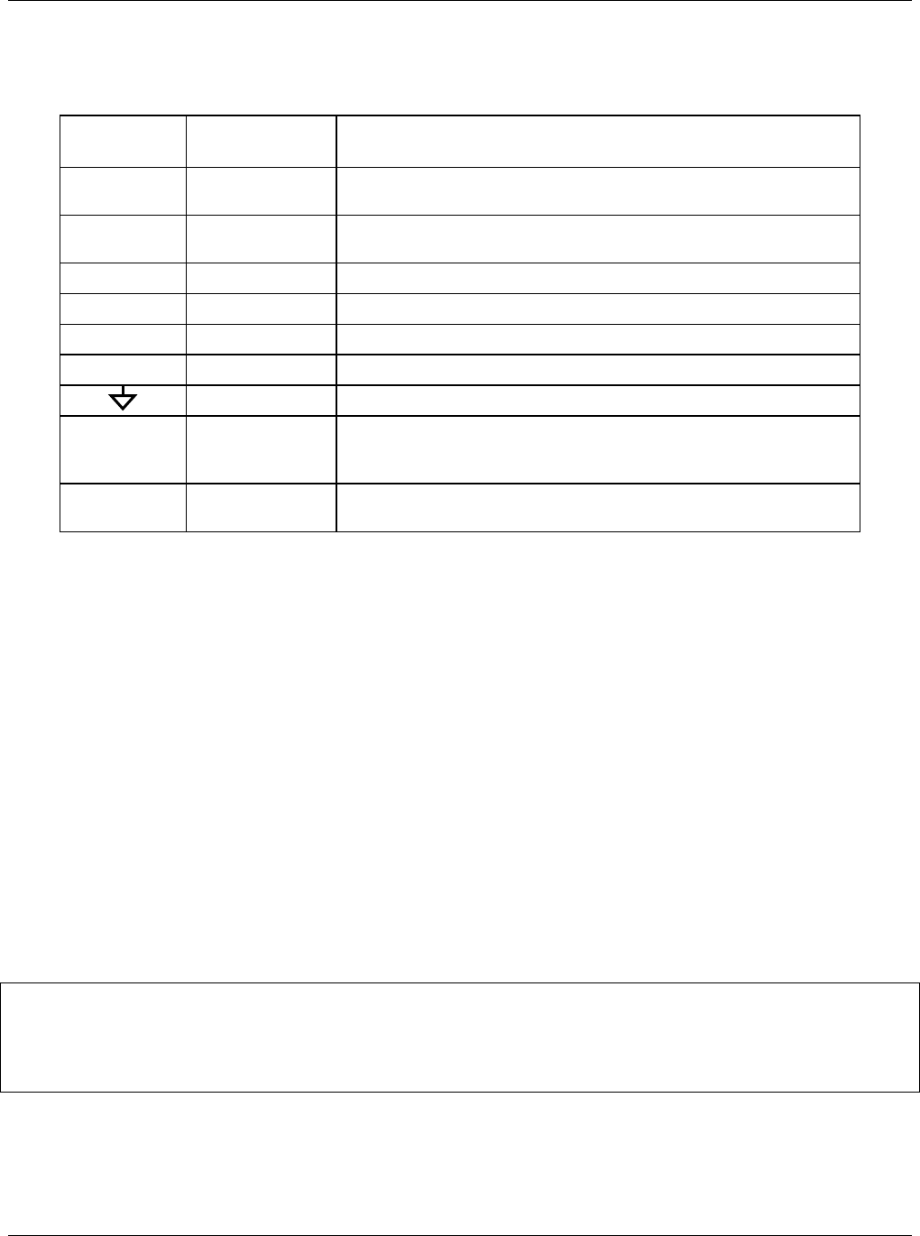
The pin assignments for the digital control inputs can be found in the table below:
Table 3-3: GFC7000E Control Input Pin Outs
Input #
Status
Definition
On Condition
A
REMOTE ZERO
CAL
The Analyzer is placed in Zero Calibration mode. The mode
field of the display will read ZERO CAL R.
B
REMOTE
SPAN CAL
The Analyzer is placed in Span Calibration mode. The mode
field of the display will read SPAN CAL R.
C
SPARE
D
SPARE
E
SPARE
F
SPARE
Digital Ground May be connected to the ground of the datalogger/recorder.
U
Pullup supply
for inputs
Input pin for +5 VDC required to activate pins A – F. This
can be from an external source or from the “+” pin of the
instruments STATUS connector.
+
Internal +5V
Supply
Internal source of +5V which can be used to actuate control
inputs when connected to the U pin.
12. If you wish to utilize either of the analyzer’s two serial interface COMM ports, refer to Section
6.10 of this manual for instructions on their configuration and usage.
13. If your unit has a Teledyne Instruments Ethernet card (Option 63), plug one end into the 7’
CAT5 cable supplied with the option into the appropriate place on the back of the analyzer
(see Figure 5-4 in Section 5.5.3) and the other end into any nearby Ethernet access port.
3.1.2. Pneumatic Connections:
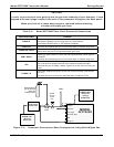
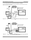
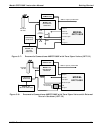
3.1.2.1. Basic Pneumatic Connections
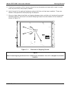
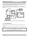
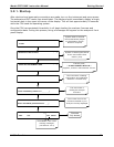
Figures 3-3 and 3-4 illustrate the most common configurations for gas supply and exhaust lines to
the Model GFC7000E Analyzer. Figure 3-13 illustrates the internal gas flow of the instrument in
its basic configuration.
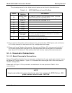
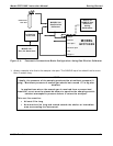
Please refer to Figure 3-2 for pneumatic connections at the rear panel and Table 3-4 for
nomenclature.
NOTE
Sample and calibration gases should only come into contact with PTFE (Teflon), FEP,
glass, stainless steel or brass. CAUTION