


Model GFC7000E Instruction Manual THEORY OF OPERATION
04584 Rev A1 169
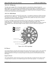
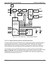
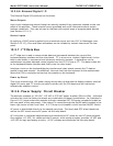
GFC Wheel Motor Control:
The GFC wheel operates from a AC voltage supplied by a multi-input transformer located on the
relay board. The step-down ratio of this transformer is controlled by factory-installed jumpers to
adjust for 100 VAC, 115 VAC or 230 VAC line power. Other circuitry slightly alters the phase of the
AC power supplied to the motor during start up based on whether line power is 50Hz or 60 Hz.
Normally, the GFC Wheel Motor is always turning while the analyzer is on. A physical switch
located on the relay board can be used to turn the motor off for certain diagnostic procedures.
Zero/Span Valve Options
Any zero/span/shutoff valve options installed in the analyzer are controlled by a set of electronic
switches located on the relay board. These switches, under CPU control, supply the +12VDC
needed to activate each valve’s solenoid.
IR Source
The Relay board supplies a constant 11.5VDC to the IR Source. Under normal operation the IR
source is always on.
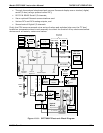
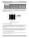
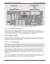
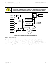
10.3.5.1. Status LED’s
Eight LED’s are located on the analyzer’s relay board to show the current status on the various
control functions performed by the relay board (see Figure 10-14). They are:
Table 10-2: Relay Board Status LED’s
LED COLOR FUNCTION STATUS WHEN LIT STATUS WHEN UNLIT
D1 RED Watchdog Circuit Cycles On/Off Every 3 Seconds under direct control of the
analyzer’s CPU.
D2 YELLOW Wheel Heater HEATING NOT HEATING
D3 YELLOW Bench Heater HEATING NOT HEATING
D4 YELLOW Spare N/A N/A
D5 GREEN Sample/Cal Gas
Valve Option
Valve Open to CAL GAS
FLOW
Valve Open to SAMPLE GAS
FLOW
D6 GREEN Zero/Span Gas
Valve Option
Valve Open to SPAN GAS
FLOW
Valve Open to ZERO GAS
FLOW
D7 GREEN Shutoff Valve
Option
Valve Open to CAL GAS
FLOW
Valve CLOSED to CAL GAS
FLOW
D8 GREEN IR SOURCE Source ON Source OFF