


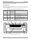
Model GFC7000E Instruction Manual Getting Started
04584 Rev A1 18
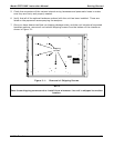
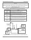
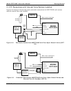
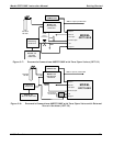
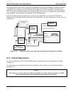
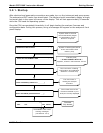
2. Attach sources of zero air and span gas (see Figures 3-3 through 3-8 inclusive).
• Span Gas is a gas specifically mixed to match the chemical composition of the type of gas
being measured at near full scale of the desired measurement range.
In the case of CO
2
measurements made with the Teledyne Analytical Instruments Model
GFC7000E Analyzer it is recommended that you use a gas calibrated to have a CO
2
content
equaling 80% of the range of compositions being measured.
EXAMPLE: If the application is to measure between 0 ppm and 500 ppm, an appropriate
Span Gas would be 400 ppm. If the application is to measure between 0 ppm and 100
ppm, an appropriate Span Gas would be 80 ppm.
• Span Gas can be purchased in pressurized canisters or created using Dynamic Dilution
Calibrator such as the Teledyne Analytical Instruments Model 700 and a source of dried
air scrubbed of CO
2
such as a Teledyne Analytical Instruments Model 701 Zero Air
Generator in combination with a canister of indicating soda-lime.
• Zero Air
is similar in chemical composition to the earths atmosphere but scrubbed of all
components that might affect the analyzer’s readings.
In the case of CO
2
measurements this means CO
2
less than 0.1 ppm of CO
2
and Water
Vapor. Zero Air can be purchased in pressurized canisters or created using a Teledyne
Instruments Model 701 Zero Air Generator in combination with a canister of indicating
soda-lime.
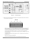
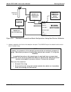
3. Attach an exhaust line to the exhaust outlet port.
• The exhaust from the pump and vent lines should be vented to atmospheric pressure using
maximum of 10 meters of ¼” PTEF tubing.
CAUTION
Venting should be outside the shelter or immediate area surrounding the
instrument.
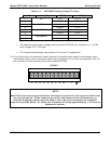
4. Attach a source of dried air scrubbed of CO
2
to the purge inlet port
NOTE
The source of purge air should be at 20-25 psig and capable of maintaining a flow of at
least 0.5 liters/min.
Purge source air pressure should not exceed 35 pisg
5. Once the appropriate pneumatic connections have been made, check all pneumatic fittings for
leaks using a procedure similar to that defined in Section 9.3.3.