


Model GFC7000E Instruction Manual Operating Instructions
04584 Rev A1 45
6. OPERATING INSTRUCTIONS
To assist in navigating the analyzer’s software, a series of menu trees can be found in Appendix
A-1 of this manual.
NOTES
The flow charts appearing in this section contain typical representations of the
analyzer’s display during the various operations being described. These representations
may differ slightly from the actual display of your instrument.
The ENTR key may disappear if you select a setting that is invalid or out of the allowable
range for that parameter, such as trying to set the 24-hour clock to 25:00:00. Once you
adjust the setting to an allowable value, the ENTR key will re-appear.
6.1. Overview of Operating modes
The MGFC7000E software has a variety of operating modes. Most commonly, the analyzer will be
operating in SAMPLE mode. In this mode, a continuous read-out of the CO
2
concentration is
displayed on the front panel and output as an analog voltage from rear panel terminals,
calibrations can be performed, and TEST functions and WARNING messages can be examined.
The second most important operating mode is SETUP mode. This mode is used for performing
certain configuration operations, such as for the iDAS system, the reporting ranges, or the serial
(RS-232/RS-485/Ethernet) communication channels. The SET UP mode is also used for
performing various diagnostic tests during troubleshooting.
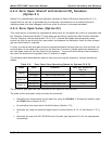
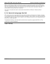
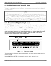
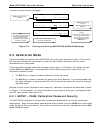
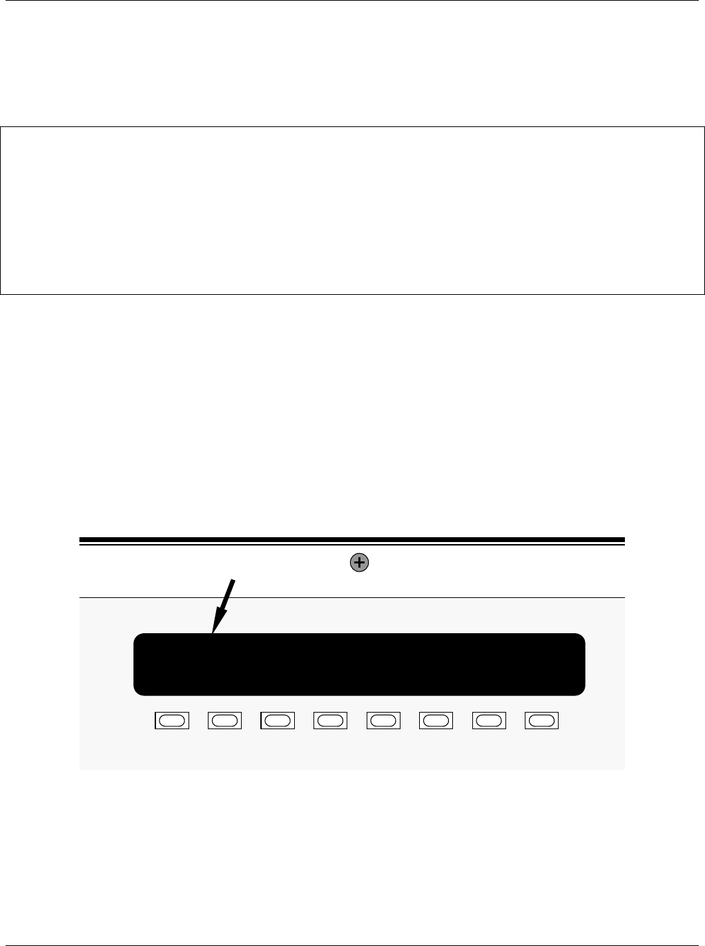
Mode Field
SAMPLE A RANGE = 500.00 PPM CO2 400.00
<TST TST> CAL SETUP
Figure 6-1: Front Panel Display
The mode field of the front panel display indicates to the user which operating mode the unit is
currently running.
Besides SAMPLE and SETUP, other modes the analyzer can be operated in are: