


Model GFC7000E Instruction Manual THEORY OF OPERATION
04584 Rev A1 171
For calibration purposes, two reference voltages are supplied to the A/D converter: Reference
Ground and +4.096 VDC. During calibration, the device measures these two voltages, outputs
their digital equivalent to the CPU. The CPU uses these values to compute the converter’s offset
and slope and uses these factors for subsequent conversions.
See Section 6.9.4 for instructions on performing this calibration.
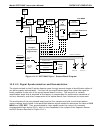
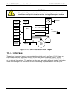
10.3.6.2. Sensor Inputs
The key analog sensor signals are coupled to the A/D through the master multiplexer from two
connectors on the motherboard. 100K terminating resistors on each of the inputs prevent cross
talk from appearing on the sensor signals.
Co
2
Measure And Reference
These are the primary signals that are used in the computation of the CO
2
concentration. They
are the demodulated IR-sensor signals from the sync demodulator board.
Sample Pressure And Flow
These are analog signals from two sensors that measure the pressure and flow rate of the gas
stream at the outlet of the sample chamber. This information is used in two ways. First, the
sample pressure is used by the CPU to calculate CO
2
Concentration. Second, the pressure and
flow rate are monitored as a test function to assist the user in predicting and troubleshooting
failures.
10.3.6.3. Thermistor Interface
This circuit provides excitation, termination and signal selection for several negative-coefficient,
thermistor temperature sensors located inside the analyzer. They are:
Sample Temperature Sensor
The source of this signal is a thermistor located inside the sample chamber of the Optical Bench.
It measures the temperature of the sample gas in the chamber. This data is used to during the
calculation of the CO
2
concentration value.
Bench Temperature Sensor
This thermistor, attached to the sample chamber housing, reports the current temperature of the
chamber housing to the CPU as part of the bench heater control loop.
Wheel Temperature Sensor
This thermistor attached a the heat-sync on the GFC wheel motor assembly reports the current
temperature of the wheel/motor assembly to the cpu as part of the Wheel Heater control loop.
Box Temperature Sensor
A thermistor is attached to the mother board. It measures the analyzer’s inside temperature.
This information is stored by the CPU and can be viewed by the user for troubleshooting purposes
via the front panel display (see Section 11.1.2).