


Model GFC7000E Instruction Manual Getting Started
04584 Rev A1 19
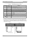
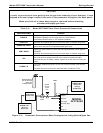
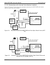
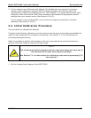
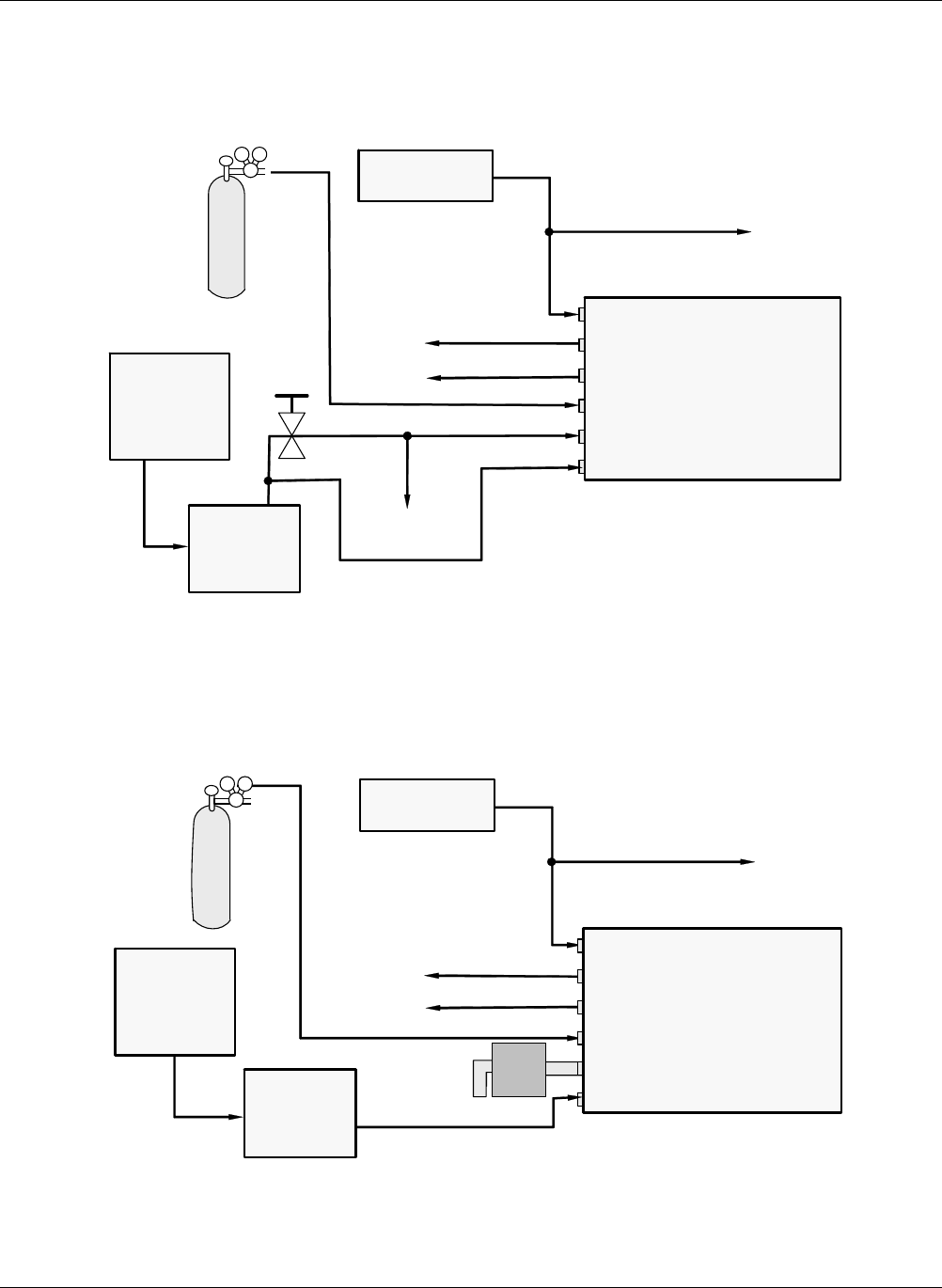
3.1.2.2. Connections with Internal Valve Options Installed
Figures 3-5 through 3-8 show the proper pneumatic connections for MGFC7000E’s with various
optional internal valve sets installed.
Source of
SAMPLE Gas
VENT
VENT
Certified
CO
2
Gas
Source of
SAMPLE Gas
VENT if input is pressurized
Needle
valve to
control
flow
MODEL
GFC7000E
Sam
p
le
IZS
Exhaust
Vent S
p
an
Pressure Span
Pur
g
e In
Indicating
soda-lime
MODEL 701
Zero Air
Generator
Figure 3-5: Pneumatic Connections–MGFC7000E with Zero/Span/Shutoff Valves (OPT
50)
VENT
Certified
CO
2
Gas
Source of
SAMPLE Gas
VENT if input is pressurized
External Zero
Air Scrubber
MODEL
GFC7000E
Sam
p
le
IZS
Exhaust
Vent S
p
an
Pressure Span
Pur
g
e In
Indicating
soda-lime
MODEL 701
Zero Air
Generator
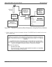
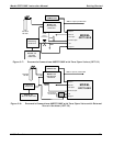
Figure 3-6 Pneumatic Connections–MGFC7000E with Zero/Span/Shutoff Valves and
External Zero Air Scrubber (OPT 51)