


Model GFC7000E Instruction Manual Calibration Procedures
04584 Rev A1 130
7.1.2. Calibration Gas Traceability
All equipment used to produce calibration gases should be verified against standards of the
National Institute for Standards and Technology (NIST). To ensure NIST traceability, we
recommend to acquire cylinders of working gas that are certified to be traceable to NIST Standard
Reference Materials (SRM). These are available from a variety of commercial sources.
7.1.3. Data Recording Devices
A strip chart recorder, data acquisition system or digital data acquisition system should be used to
record data from the MGFC7000E’s serial or analog outputs. If analog readings are used, the
response of the recording system should be checked against a NIST traceable voltage source or
meter. Data recording device should be capable of bi-polar operation so that negative readings
can be recorded. For electronic data recording, the MGFC7000E provides an internal data
acquisition system (iDAS), which is described in detail in Section 6.12.
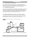
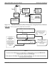
7.2. Manual Calibration without Zero/Span Valves
This is the basic method for manually calibrating the Model GFC7000E CO
2
Analyzer without
functioning zero/span valve options. It is identical to the method described in the GETTING
STARTED (Chapter 3) of this manual and is repeated her for you convenience.
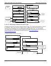
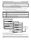
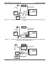
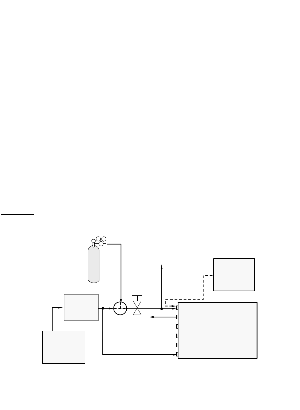
STEP ONE
: Connect the Sources of Zero Air and Span Gas as shown below.
VENT
Calibrated CO
2
gas at desired
span gas
concentration
Source of
SAMPLE Gas
Removed
during
Calibration
Valve
Needle
valve to
control
flow
MODEL
GFC7000E
Sam
p
le
IZS
Exhaust
Vent S
p
an
Pressure Span
Pur
g
e In
Indicating
soda-lime
MODEL 701
Zero Air
Generator
Figure 7-1: Pneumatic Connections–Basic Configuration–Using Bottled Span Gas