Model GFC7000E Instruction Manual THEORY OF OPERATION
04584 Rev A1 175
Mother
Board
Status Outputs:
1 – 8
Control Inputs:
1 – 6
CPU
RS–232 ONLY
RS-232 or RS–485
KEYBOARD
RELAY
BOARD
PC/104 BUS
FRONT PANEL DISPLAY
I
2
C BUS
I
2
C BUS
Analog Outputs
A1
A2
A3
Optional
4-20 mA
COMM B
Female
A4ST
COMM A
Male
ETHERNET
OPTION
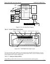
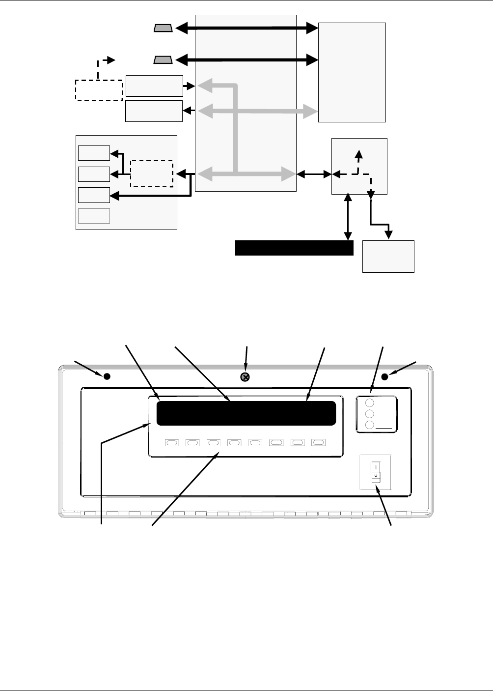
Figure 10-16: Interface Block Diagram
10.4.1. Front Panel Interface
MODE FIELD
KEY DEFINITIONS
MESSAGE FIELD
CONCENTRATION FIELD
STATUS LED’s
KEYBOARD ON / OFF SWITCH
FASTENER FASTENER
POWER
FAULT
CAL
SAMPLE
GAS FILTER CORRELATION CO
2
ANALYZER- MODEL GFC7000E
SAMPLE A
RANGE = 500.0 PPM
CO2 = 400.0
<TST
TST> CAL
SETUP
LOCKING SCREW
Figure 10-17: GFC7000E Front Panel Layout
The most commonly used method for communicating with the MGFC7000E Analyzer is via the
instrument’s front panel which includes a set of three status LEDs, a vacuum florescent display
and a keyboard with 8 context sensitive keys.
10.4.1.1. Analyzer Status LED’s
Three LEDS are used to inform the user of the instruments basic operating status


