Model GFC7000E Instruction Manual GFC7000E Documentation
04584 Rev A1 iii
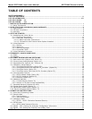
6.7. SETUP – RNGE: Analog Output Reporting Range Configuration.....................................................56
6.7.1. Physical Range versus Analog Output Reporting Ranges........................................................56
6.7.2. Reporting Range Modes ...................................................................................................57
6.7.3. Single Range mode (SNGL) ..............................................................................................58
6.7.4. Dual Range Mode (DUAL) .................................................................................................60
6.7.5. Auto Range Mode (AUTO).................................................................................................61
6.7.6. Range Units ...................................................................................................................62
6.7.7. Dilution Ratio .................................................................................................................63
6.8. SETUP – VARS: Using the Internal Variables..............................................................................64
6.9. SETUP – DIAG: Using the Diagnostics Functions.........................................................................66
6.9.1. Accessing the Diagnostic Features .....................................................................................67
6.9.2. Signal I/O ......................................................................................................................67
6.9.3. Analog Output Step Test ..................................................................................................68
6.9.4. Analog I/O Configuration..................................................................................................69
6.9.4.1. Analog Output Signal Type and Range Span Selection ....................................................71
6.9.4.2. Analog Output Calibration Mode..................................................................................71
6.9.4.3. Manual Analog Output Calibration and Voltage Adjustment .............................................73
6.9.4.4. Current Loop Output Adjustment.................................................................................75
6.9.4.5. AIN Calibration.........................................................................................................77
6.9.5. Electric Test ...................................................................................................................77
6.9.6. Dark Calibration Test .......................................................................................................78
6.9.7. Pressure Calibration ........................................................................................................78
6.9.8. Flow Calibration ..............................................................................................................80
6.9.9. Test Channel Output........................................................................................................81
6.10. SETUP – COMM: Using the Analyser’s Communication Ports .......................................................82
6.10.1. Analyzer ID Code ..........................................................................................................82
6.10.2. COMM Port Default Settings ............................................................................................83
6.10.3. COMM Port Cable Connections.........................................................................................84
6.10.4. RS-485 Configuration of COM2 ........................................................................................84
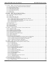
6.10.5. DTE and DCE Communication..........................................................................................85
6.10.6. COMM Port Communication Modes ...................................................................................85
6.10.7. COM Port Baud Rate ......................................................................................................88
6.10.8. COM Port Testing ..........................................................................................................89
6.10.9. Ethernet Card Configuration............................................................................................89
6.10.9.1. Ethernet Card COM2 Communication Modes and Baud Rate...........................................90
6.10.9.2. Configuring the Ethernet Interface Option using DHCP..................................................90
6.10.9.3. Manually Configuring the Network IP Addresses...........................................................92
6.10.9.4. Changing the Analyzer’s HOSTNAME ..........................................................................94
6.11. SETUP – ALRM: Using the Gas Concentration Alarms.................................................................95
6.12. SETUP – DAS: Using the Data Acquisition System (iDAS)...........................................................96
6.12.1. iDAS Structure..............................................................................................................96
6.12.1.1. iDAS Channels........................................................................................................97
6.12.1.2. iDAS Parameters.....................................................................................................98
6.12.1.3. iDAS Triggering Events ............................................................................................98
6.12.2. Default iDAS Channels ...................................................................................................99
6.12.2.1. Viewing iDAS Data and Settings .............................................................................. 103
6.12.2.2. Editing iDAS Data Channels .................................................................................... 104
6.12.2.3. Trigger Events...................................................................................................... 105
6.12.2.4. Editing iDAS Parameters ........................................................................................ 106
6.12.2.5. Sample Period and Report Period............................................................................. 107
6.12.2.6. Number of Records ............................................................................................... 109
6.12.2.7. RS-232 Report Function ......................................................................................... 110
6.12.2.8. Compact Report.................................................................................................... 111
6.12.2.9. Starting Date ....................................................................................................... 111
6.12.2.10. Disabling/Enabling Data Channels.......................................................................... 111
6.12.2.11. HOLDOFF Feature................................................................................................ 112
6.12.3. Remote iDAS Configuration........................................................................................... 113
6.13. Remote Operation of the Analyzer........................................................................................ 115
6.13.1. Remote Operation Using the External Digital I/O.............................................................. 115
6.13.1.1. Status Outputs ..................................................................................................... 115


