


Model GFC7000E Instruction Manual THEORY OF OPERATION
04584 Rev A1 168
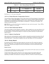
Table 10-1: Sync/Demod Status LED Activity
LED FUNCTION STATUS OK FAULT STATUS
D1 M/R Sensor Status LED flashes approximately
2/second
LED is stuck
ON or OFF
D2 Segment Sensor
Status
LED flashes approximately
6/second
LED is stuck
ON or OFF
See Section 11.1.4 for more information.
10.3.4.5. Photo-Detector Temperature Control
The synch/demod board also contains circuitry that controls the IR photo-detector’s thermoelectric
coolers. A drive voltage, PHT DRIVE, is supplied to the coolers by the synch/demod board which
is adjusted by the synch/demod board based on a return signal called TEC control which alerts
informs the synch/demod board of the detector’s temperature. The warmer the detector, the
harder the coolers are driven.
PHT DRIVE is one of the Test Functions viewable by the user via the form panel. Press <TST or
TST> until it appears on the display.
10.3.4.6. Dark Calibration Switch
This switch initiates the Dark Calibration procedure. When initiated by the user (see Section 6.9.6
for more details), the dark calibration process opens this switch, interrupting the signal from the
IR photo-detector. This allows the analyzer to measure any offset caused by the synch/demod
board circuitry.
10.3.4.7. Electric Test Switch
When active this circuit generates a specific waveform intended to simulate the function of the IR
photo-detector but with a known set of value which is substituted for the detector’s actual signal
via the dark switch. It may also be initiated by the user (see Section 6.9.5 for more details).
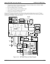
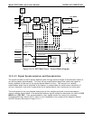
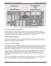
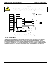
10.3.5. Relay Board
By actuating various switches and relays located on this board, the CPU controls the status of
other key components. The relay board receives instructions in the form of digital signals over
the I
2
C bus, interprets these digital instructions and activates its various switches and relays
appropriately.
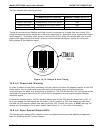
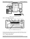
Heater Control
The two heaters attached to the sample chamber housing and the GFC wheel motor are controlled
by solid state relays located on the relay board.
The GFC wheel heater is simply turned on or off, however control of the bench heater also
includes circuitry that selects which one of its two separate heating elements is activated
depending on whether the instrument is running on 100 VAC, 115 VAC or 230 VAC line power.