


Model GFC7000E Instruction Manual TROUBLESHOOTING & REPAIR PROCEDURES
04584 Rev A1 199
MGFC7000E Final Test And Validation Data Sheet-p/n 04271 shipped with the unit from Teledyne
Instruments).
1. The most common cause of excessive noise is leaks. Leak check and flow check the
instrument described in Section 9.3.
2. Detector failure – caused by failure of the hermetic seal or over-temperature due to poor heat
sinking of the detector can to the optical bench. In addition to increased noise due to poor
signal-to-noise ratio, another indicator of detector failure is a drop in the signal levels of the
CO
2
MEASURE signal and CO
2
REFERENCE signal.
3. Sync/Demod Board failure. There are many delicate, high impedance parts on this board.
Check the CO2 MEAS and CO2 REF Test Functions via the Front Panel Display.
4. The detector cooler control circuit can fail for reasons similar to the detector itself failing.
Symptoms would be a change in MR RATIO Test Function when zero air is being sampled.
Also check the SIGNAL I/O parameter PHT DRIVE. After warm-up, and at 25
o
C ambient, if
PHT DRIVE < 2500 mV, the cooler is working properly. If PHT DRIVE is > 2500 mV there is a
malfunction.
5. The +5 and ±15 VDC voltages in the MGFC7000E are provided by switching power supplies.
Switch mode supplies create DC outputs by switching the input AC waveform at high
frequencies. As the components in the switcher age and degrade, the main problem observed
is increased noise on the DC outputs. If a noisy switcher power supply is suspected, attach an
oscilloscope to the DC output test points located on the top right hand edge of the Relay
board. Look for short period spikes > 100 mV p-p on the DC output.
11.4. Subsystem Checkout
The preceding sections of this manual discussed a variety of methods for identifying possible
sources of failures or performance problems within the analyzer. In most cases this included a list
of possible causes. This section describes how to determine individually determine if a certain
component or subsystem is actually the cause of the problem being investigated.
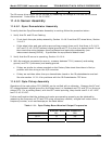
11.4.1. AC Mains Configuration
The analyzer is correctly configured for the AC mains voltage in use if:
1. The Sample Pump is running.
2. The GFC wheel motor is spinning (a slight vibration should be apparent to the touch).
3. If incorrect power is suspected, check that the correct voltage and frequency is present at the
line input on the rear panel.
• If the unit is set for 230 VAC and is plugged into 115VAC, or 100VAC the sample pump
will not start, and the heaters will not come up to temperature.
• If the unit is set for 115 or 100 VAC and is plugged into a 230 VAC circuit, the circuit
breaker built into the ON/OFF Switch on the Front Panel will trip to the OFF position
immediately after power is switched on.