


Model GFC7000E Instruction Manual THEORY OF OPERATION
04584 Rev A1 159
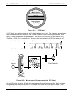
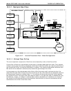
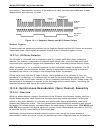
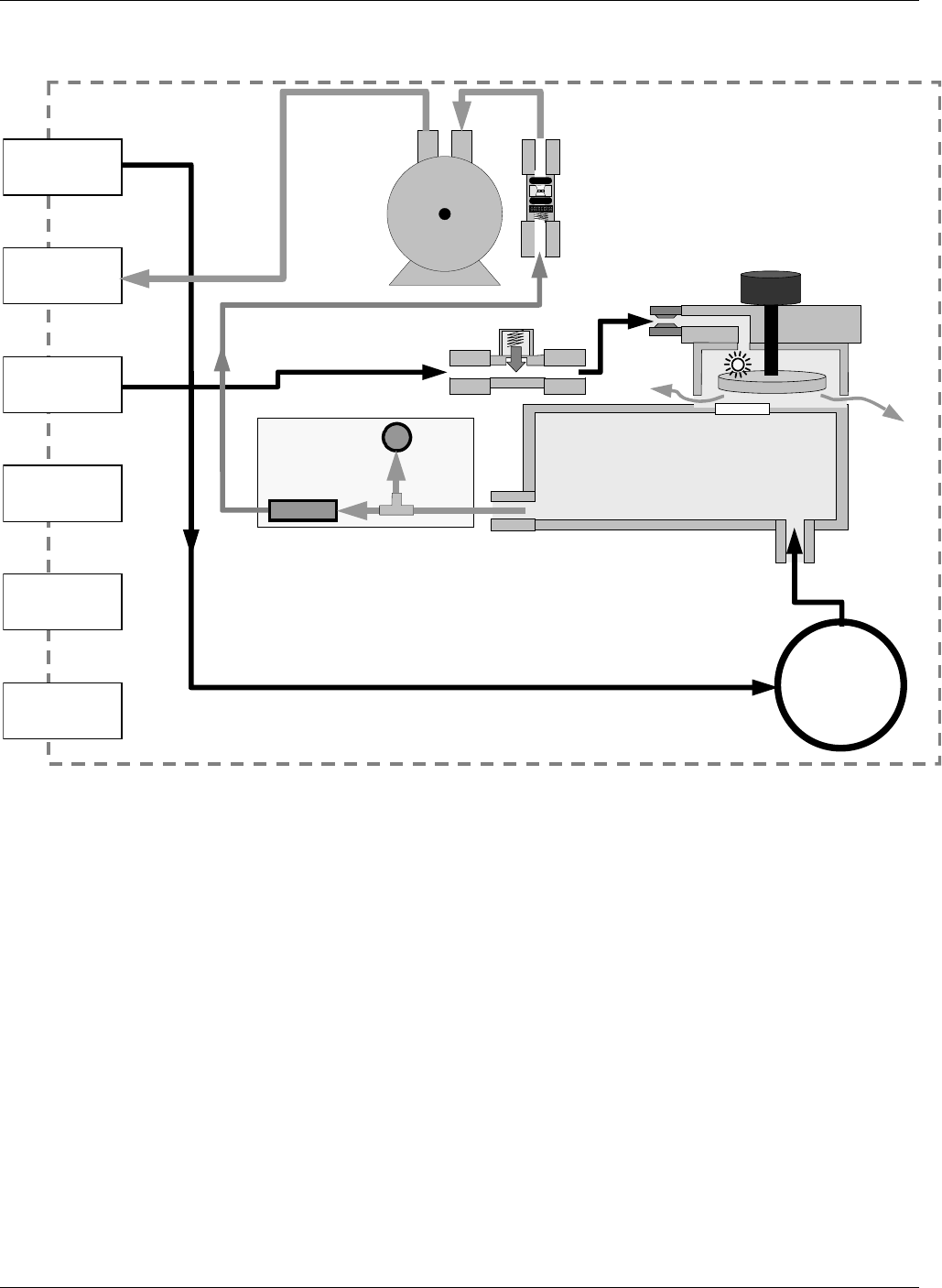
10.2.1. Sample Gas Flow
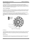
GFC Wheel
Motor
PARTICULATE
FILTER
INSTRUMENT CHASSIS
PUMP
GFC Wheel
Housing
SAMPLE CHAMBER
GFC Motor
Heat Sync
V
ENT SPAN
OUTLET
PRESSURE
SPAN INLET
IZS INLET
EXHAUST GAS
OUTLET
PURGE GAS
INLET
SAMPLE GAS
INLET
Purge Gas
Flow Rate
Control
Orifice
Purge Gas
Pressure
Control Assy
Sample Gas Critical
Flow Orifice
FLOW
SENSOR
SAMPLE
PRESSURE
SENSOR
FLOW / PRESSURE
SENSOR PCA
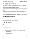
Figure 10-7: Internal Pneumatic Flow – Basic Configuration
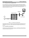
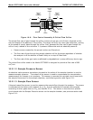
10.2.1.1. Critical Flow Orifice
The most important component of this flow control assembly is the critical flow orifice.
Critical flow orifices are a remarkably simple way to regulate stable gas flow rates. They operate
without moving parts by taking advantage of the laws of fluid dynamics. By restricting the flow of
gas though the orifice, a pressure differential is created. This pressure differential combined with
the action of the analyzer’s external pump draws the gas through the orifice.
As the pressure on the downstream side of the orifice (the pump side) continues to drop, the
speed that the gas flows though the orifice continues to rise. Once the ratio of upstream pressure
to downstream pressure is greater than 2:1, the velocity of the gas through the orifice reaches
the speed of sound. As long as that ratio stays at least 2:1 the gas flow rate is unaffected by any
fluctuations, surges, or changes in downstream pressure because such variations only travel at
the speed of sound themselves and are therefore cancelled out by the sonic shockwave at the
downstream exit of the critical flow orifice.