


Model GFC7000E Instruction Manual THEORY OF OPERATION
04584 Rev A1 166
Thermo-Electric
Cooler
Control Circuit
Sample
&
Hold
Circuits
(x4)
Amplifiers
Dark
Switch
Photo-
detector
Pre
Amp
Phase
Lock
Loop
E-Test
Generator
Compact
Programmable
Logic Device
M/R Senso
r
Segment
Sensor
E Test Control
Dark Switch
Control
X10 Cloc
k
Phase Lock
E Test A Gate
Dark Test Gate
X1 Reference
Segment
Status LED
Phase Lock Warning
M/R
Status LED
Segment Clock
E Test B Gate
Measure Gate
Measure Dark Gate
Reference Gate
Reference Dark Gate
CO
2
MEAS
CO
2
Reference
56V
Bias
Variable
Gain Amp
From GFC
Wheel
From CPU
via Mother
Board
Signal
Conditioner
Signal
Conditioner
÷
10
x10
TEC Control
PHT DRIVE
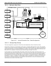
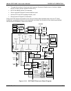
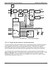
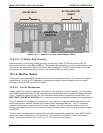
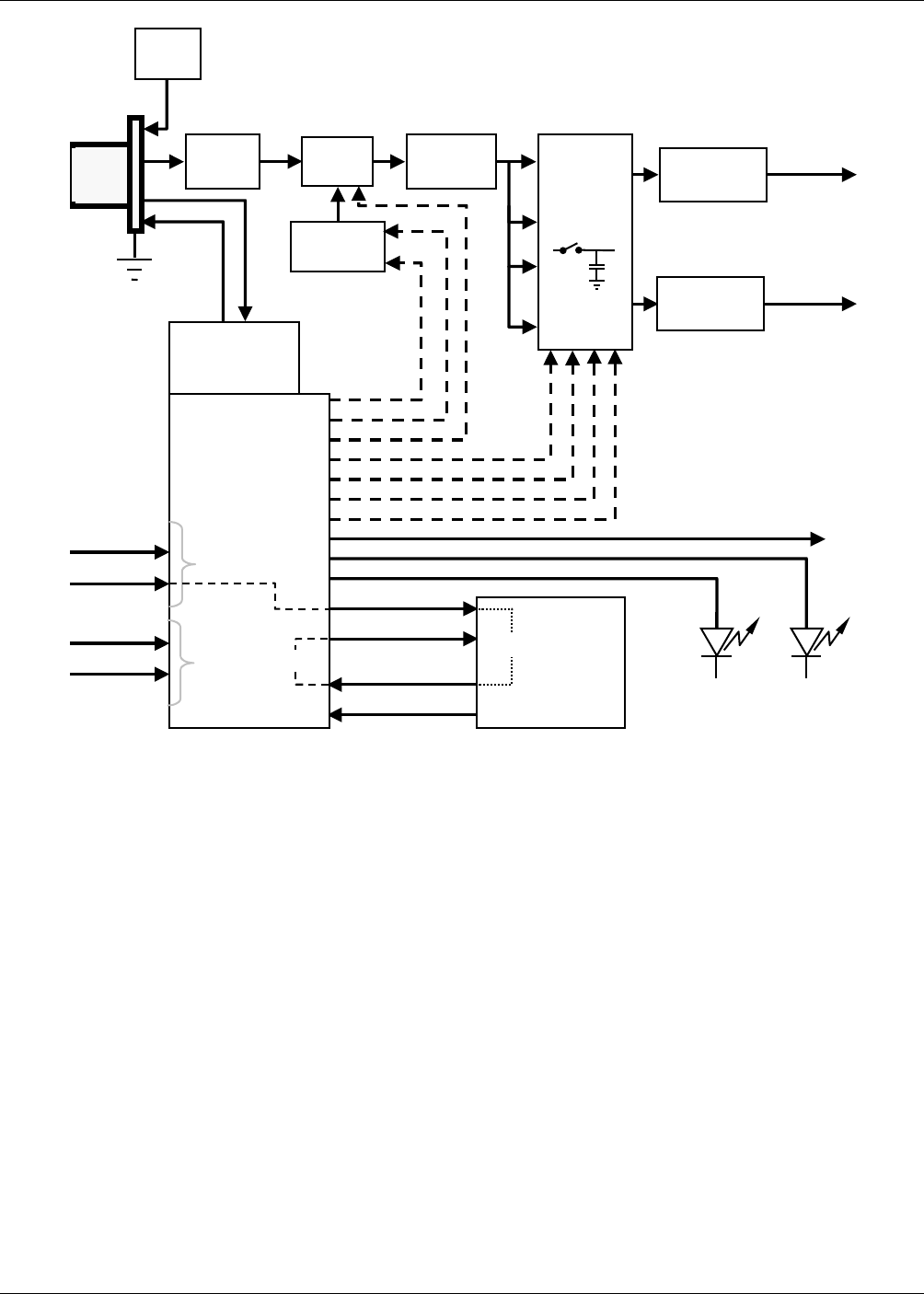
Figure 10-12: GFC7000E Sync / Demod Block Diagram
10.3.4.2. Signal Synchronization and Demodulation
The signal emitted by the IR photo-detector goes through several stages of amplification before it
can be accurately demodulated. The first is a pre-amplification stage that raises the signal to
levels readable by the rest of the synch/demod board circuitry. The second is a variable
amplification stage that is adjusted at the factory to compensate for performance variations of
mirrors, detectors, and other components of the optical bench from instrument to instrument.
The workhorses of the sync/demod board are the four sample-and-hold circuits that capture
various voltage levels found in the amplified detector signal needed to determine the value of CO2
MEAS and CO2 REF. They are activated by logic signals under the control of a compact
programmable logic device (PLD), which in turn responds to the output of the Segment Sensor
and M/R Sensor described in Figure 10–11.