Model GFC7000E Instruction Manual TROUBLESHOOTING & REPAIR PROCEDURES
04584 Rev A1 198
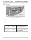
11.3.1.3. GFC Wheel Temperature
Like the bench heater above there are three possible causes for the GFC wheel temperature to
have failed.
1. The wheel heater has failed. Check the resistance between pins 1 and 4 on the white five-pin
connector just below the sample temperature sensor on the bench (pin 1 is the pointed end).
It should be approximately 275 ohms.
2. Assuming that the I
2
C buss is working and that there is no other failure with the relay board,
the solid-state relay (K1) on the relay board may have failed. Using the WHEEL_HEATER
parameter under the signal I/O function, as described above, turn on and off K1 (D2 on the
relay board should illuminate as the heater is turned on). Check the AC voltage present
between pin 1 and 4.
WARNING:
HAZARDOUS VOLTAGES ARE PRESENT DURING THIS TEST
3. If the relay has failed there should be no change in the voltage across pins 1 and 4. Note, K1
is socketed for easy replacement.
4. If K1 checks out OK, the thermistor temperature sensor located at the front of the filter wheel
assembly may have failed. Unplug the connector labeled “Wheel”, and measure the resistance
of the thermistor. The resistance near the 68
o
C set point is ~5.7k ohms.
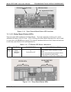
11.3.1.4. IR Photo-Detector TEC Temperature
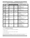
If the PHT DRIVE test parameter described above in Table 11-2 is out of range there are two
four possible causes of failure.
1. The screws retaining the IR photo detector to the absorption bench have become loose.
Carefully tighten the screws, hand-tight and note whether, after the analyzer has come up to
operating temperature, whether the PHT DRIVE voltage has returned to an acceptable level.
2. The two large transistor-type devices mounted to the side of the Absorption Bench have come
loose from the bench. Tighten the retaining screws and note whether there is an improvement
in the PHT DRIVE voltage.
3. The photo-detector has failed. Contact the factory for instructions.
4. The sync demodulator circuit board has failed. Contact the factor for instructions.
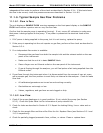
11.3.2. Excessive Noise
Noise is continuously monitored in the TEST functions as the STABIL reading and only becomes
meaningful after sampling a constant gas concentration for at least 10 minutes. Compare the
current STABIL reading with that recorded at the time of manufacture (included in the


