


Model GFC7000E Instruction Manual Operating Instructions
04584 Rev A1 56
6.7. SETUP – RNGE: Analog Output Reporting Range
Configuration
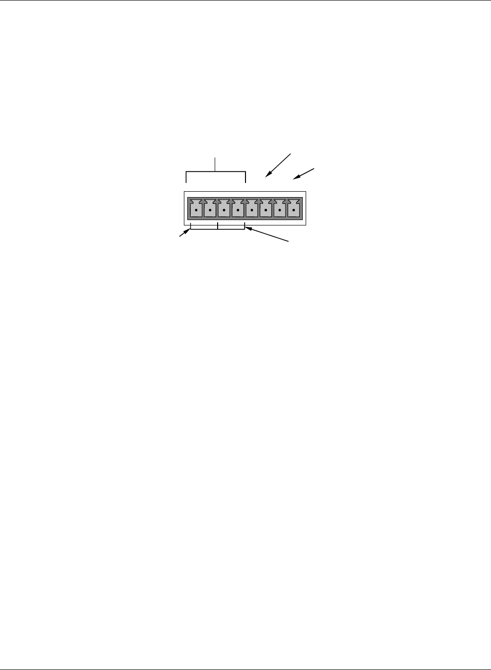
The analyzer has three active analog output signals, accessible through a connector on the rear
panel.
Test Channe
l
ANALOG OUT
A1 A2 A3 A4
+ - + - + - + -
SO
2
concentration
out
p
uts
HIGH range when
DUAL mode is selecte
d
Not Used
LOW range when
DUAL mode is selecte
d
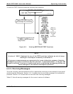
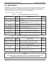
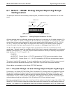
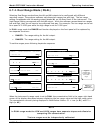
Figure 6-4: Analog Output Connector Pin Out
All three outputs can be configured either at the factory or by the user for full scale outputs of 0.1
VDC, 1VDC, 5VDC or 10VDC. Additionally A1 and A2 may be equipped with optional 0-20 mADC
current loop drivers and configured for any current output within that range (e.g. 0-20, 2-20, 4-
20, etc.). The user may also adjust the signal level and scaling of the actual output voltage or
current to match the input requirements of the recorder or datalogger (see Section 6.9.4).
The A1 and A2 channels output a signal that is proportional to the CO
2
concentration of the
sample gas. Several modes are available which allow them to operate independently or be slaved
together (see Section 6.7). The user may also select between a variety of reporting range spans
(see Sections 6.7.3, 6.7.4 and 6.7.5).
EXAMPLE:
A1 OUTPUT: Output Signal = 0-5 VDC representing 0-1000 ppm concentration values
A2 OUTPUT: Output Signal = 0 – 10 VDC representing 0-500 ppm concentration values.
The output, labeled A3 is special. It can be set by the user (see Section 6.9.9) to output several
of the test functions accessible through the <TST TST> keys of the units sample display.
Output A4 is not available on the Model GFC7000E analyzer.
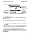
6.7.1. Physical Range versus Analog Output Reporting Ranges
Functionally, the Model GFC7000E Gas Filter Correlation CO
2
Analyzer has one hardware Physical
Range that is capable of determining CO
2
concentrations between 50 ppb and 2 000 ppm. This
architecture improves reliability and accuracy by avoiding the need for extra, switchable, gain-
amplification circuitry. Once properly calibrated, the analyzer’s front panel will accurately report
concentrations along the entire span of its 50 ppb and 2 000 ppm physical range.
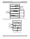
Because, most applications use only a small part of the analyzer’s physical range, the width of the
Model GFC7000E’s physical range can create data resolution problems for most analog recording
devices. For example, in an application where the expected concentration of CO
2
is typically less