Model GFC7000E Instruction Manual Optional Hardware and Software
04584 Rev A1 39
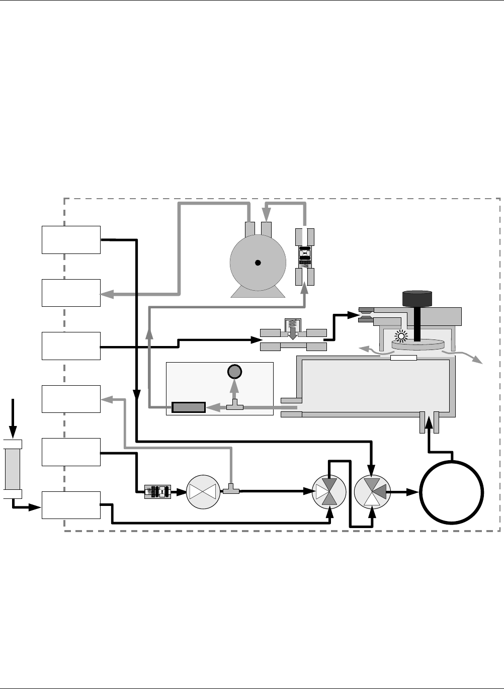
The state of the zero/span valves can also be controlled:
• Manually from the analyzer’s front panel by using the SIGNAL I/O controls located under
the DIAG Menu (Section 6.9.2),
• By activating the instrument’s AutoCal feature (Section 7.6),
• Remotely by using the external digital control inputs (Section 6.13.1.2 and Section 7.5.2),
or
• Remotely through the RS-232/485 serial I/O ports (see Appendix A-6 for the appropriate
commands).
FLOW / PRESSURE
SAMPLE
SENSOR PCA
PRESSURE
SENSOR
FLOW
SENSOR
INSTRUMENT CHASSIS
PUMP
SAMPLE CHAMBER
V
ENT SPAN
OUTLET
PRESSURE
SPAN INLET
IZS INLET
EXHAUST GAS
OUTLET
PURGE GAS
INLET
SAMPLE GAS
INLET
Sample Gas Critical
Flow Orifice
GFC Wheel
Motor
GFC Motor
Heat Sync
GFC Wheel
Housing
Purge Gas
Pressure
Control Assy
PARTICULATE
FILTER
SHUT OFF
VALVE
1
2
SAMPLE /CAL
VALVE
3
2
1
Purge Gas
Flow Control
Orifice
ZERO/SPAN
VALVE
2
1
3
external CO
2
Scrubber
(Opt 53 Only)
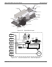
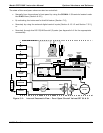
Figure 5-2: Internal Pneumatic Flow – Zero/Span/Shutoff Valves OPT 50 & 51


