


Model GFC7000E Instruction Manual TROUBLESHOOTING & REPAIR PROCEDURES
04584 Rev A1 191
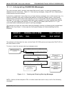
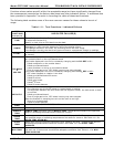
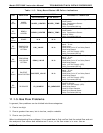
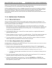
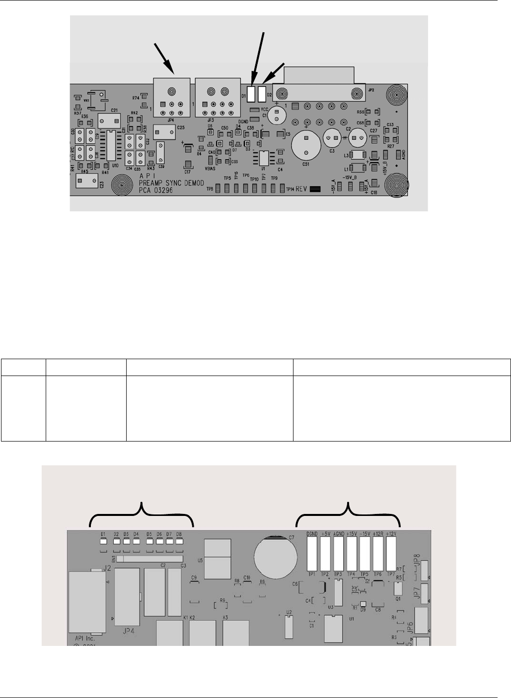
D1 – M/R Sensor Status
D2 – Segment Sensor Status
JP4 Connector to Opto-Pickup
Board
Figure 11-4: Sync/Demod Board Status LED Locations
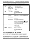
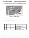
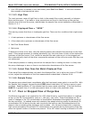
11.1.4.3. Relay Board Status LED’s
There are eight LED’s located on the Relay Board. The most important of which is D1, which
indicates the health of the I
2
C buss. If D1 is blinking the other faults following LED’s can be used
in conjunction with DIAG menu signal I/O to identify hardware failures of the relays and switches
on the relay (see Section 6.9.2 and Appendix D).
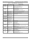
Table 11-4:
I
2
C Status LED Failure Indications
LED FUNCTION FAULT STATUS INDICATED FAILURE(S)
D1
(Red)
I2C buss
Health
(Watchdog
Circuit)
Continuously ON
or
Continuously OFF
Failed/Halted CPU
Faulty Mother Board, Keyboard or Relay
Board
Faulty Connectors/Wiring between Mother
Board, Keyboard or Relay Board
Failed/Faulty +5 VDC Power Supply (PS1)
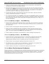
STATUS LED’s
DC VOLTAGE TEST
POINTS
RELAY PCA
PN 04135
Figure 11-5: Relay Board Status LEDs