


Model GFC7000E Instruction Manual Operating Instructions
04584 Rev A1 46
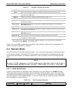
Table 6-1: Analyzer Operating modes
MODE MEANING
DIAG One of the analyzer’s diagnostic modes is being utilized (see Section 6.9).
M-P CAL This is the basic, multi-point calibration mode of the instrument and is activated
by pressing the CAL key.
SAMPLE Sampling normally, flashing indicates adaptive filter is on.
SAMPLE A Indicates that unit is in SAMPLE Mode and AUTOCAL feature is activated.
SETUP
1
SETUP mode is being used to configure the analyzer (CO
2
sampling will continue
during this process).
SPAN CAL A Unit is performing span cal procedure initiated automatically by the analyzer’s
AUTOCAL feature.
SPAN CAL M Unit is performing span cal procedure initiated manually by the user.
SPAN CAL R Unit is performing span cal procedure initiated remotely via the RS-232, RS-4485
or digital i/o control inputs.
ZERO CAL A Unit is performing zero cal procedure initiated automatically by the analyzer’s
AUTOCAL feature.
ZERO CAL M Unit is performing zero cal procedure initiated manually by the user.
ZERO CAL R Unit is performing zero cal procedure initiated remotely via the RS-232, RS-4485
or digital I/O control inputs.
1
The revision of the Teledyne Instruments software installed in this analyzer will be displayed
following the word SETUP. E.g. “SETUP
E.0”
Finally, the various CAL modes allow calibration of the analyzer. Because of its importance, this
mode is described separately in Chapter 7.
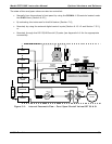
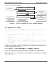
6.2. Sample Mode
This is the analyzer’s standard operating mode. In this mode the instrument is analyzing the gas
in the sample chamber, calculating CO
2
concentration and reporting this information to the user
via the front panel display, the analog outputs and, if set up properly, the RS-232/485/Ethernet
ports.
NOTE
A value of “XXXX” displayed in the CO2 Concentration field means that the M/R ratio is
invalid because CO2 REF is either too high(> 4950 mVDC) or too low (< 1250 VDC).
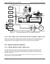
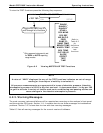
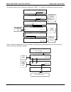
6.2.1. Test Functions
A series of test functions is available at the front panel while the analyzer is in SAMPLE mode.
These parameters provide information about the present operating status of the instrument and
are useful during troubleshooting (Section 11.1.2 ). They can also be recorded in one of the iDAS
channels (Section 6.12) for data analysis. To view the test functions, press one of the <TST TST>
keys repeatedly in either direction.
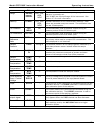
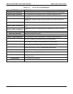
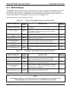
Table 6-2: Test Functions Defined
Parameter
Display
Units Meaning