


Model GFC7000E Instruction Manual TROUBLESHOOTING & REPAIR PROCEDURES
04584 Rev A1 207
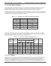
Problems with RS-232 connections usually center around 4 general areas:
1. Incorrect cabling and connectors. See Table 6-15 for connector and pin-out information.
2. The BAUD rate and protocol are incorrectly configured. See Section 6.10.7.
3. If a modem is being used, additional configuration and wiring rules must be observed. See
Section 6.13.2.6
4. Incorrect setting of the DTE – DCE Switch is set correctly See Section 6.10.5
5. Verify that cable (03596) that connects the serial COM ports of the CPU to J12 of the
Motherboard is properly seated
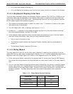
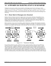
11.4.9.2. Troubleshooting Analyzer/Modem or Terminal Operation
These are the general steps for troubleshooting problems with a modem connected to a Teledyne
Instruments analyzer.
1. Check Cables for proper connection to the modem, terminal or computer.
2. Check to make sure the DTE-DCE is in the correct position as described in Section 6.10.5.
3. Check to make sure the set up command is correct (See Section 6.13.2.7)
4. Verify that the Ready to Send (RTS) signal is at logic high. The MGFC7000E sets pin 7 (RTS) to
greater than 3 volts to enable modem transmission.
5. Make sure the BAUD rate, word length, and stop bit settings between modem and analyzer
match, see Section 6.10.7.
6. Use the RS-232 test function to send “w” characters to the modem, terminal or computer; See
Section 6.10.8.
7. Get your terminal, modem or computer to transmit data to the analyzer (holding down the
space bar is one way); the green LED should flicker as the instrument is receiving data.
8. Make sure that the communications software or Terminal emulation software is functioning
properly.
Further help with serial communications is available in a separate manual “RS-232 Programming
Notes” Teledyne Instruments part number 013500000.
11.5. Repair Procedures
This section contains procedures that might need to be performed on rare occasions when a major
component of the analyzer requires repair or replacement.
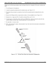
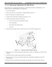
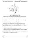
11.5.1. Repairing Sample Flow Control Assembly
The Critical Flow Orifice is housed in the Flow Control Assembly (Teledyne Instruments part
number: 001760400) located on the top of the optical bench. A sintered filter protects the jewel
orifice so it is unusual for the orifice to need replacing, but if does, or the filter needs replacement