Model GFC7000E Instruction Manual Operating Instructions
04584 Rev A1 95
Some keys only appear as needed.
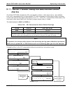
6.11. SETUP – ALRM: Using the Gas Concentration
Alarms
The Model GFC7000E includes two CO
2
concentration alarms Each alarm has a user settable
limit, and is associated with an opto-isolated TTL relay accessible via the status output connector
on the instrument’s back panel (see Section 6.13.1.1). If the CO
2
concentration measured by the
instrument rises above that limit, the alarm‘s status output relay is closed.
The default settings for ALM1 and ALM2 are:
Table 6-20: CO
2
Concentration Alarm Default Settings
ALARM STATUS
LIMIT SET POINT
1
ALM1 Disabled 100 ppm
ALM2 Disabled 300 ppm
1
Set points listed are for PPM. Should the reporting range units of measure be changed (see Section
6.7.6) the analyzer will automatically scale the set points to match the new range unit setting.
Note
To prevent the concentration alarms from activating during span calibration operations
make sure to press CAL or CALS button prior to introducing span gas into the analyzer.
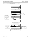
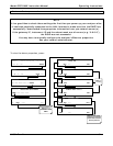
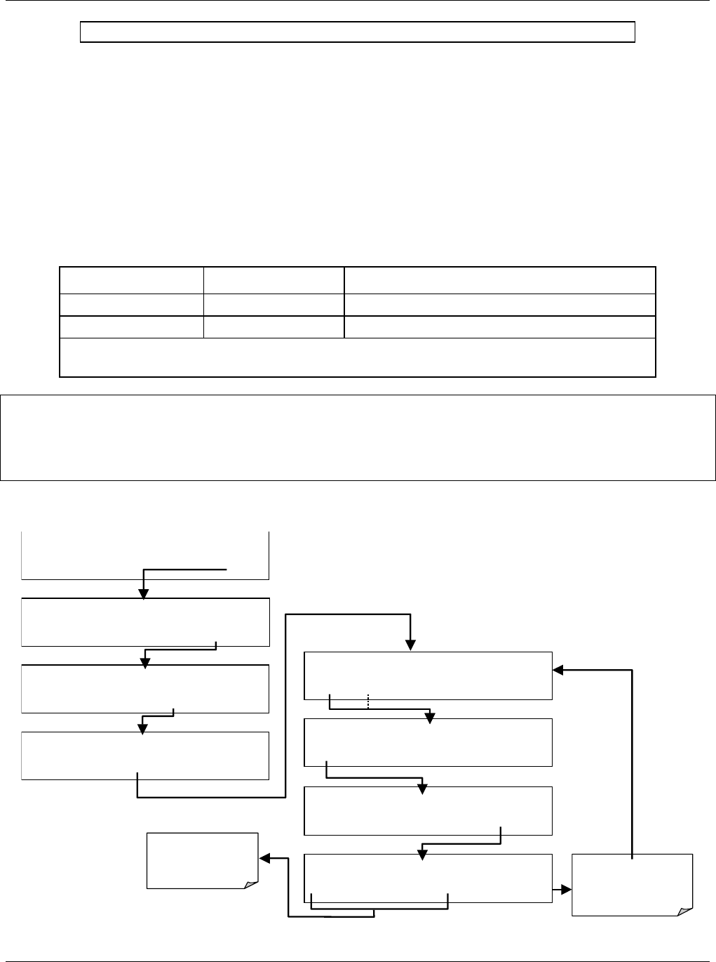
To enable either of the CO
2
concentration alarms and set the Limit points, press:
ENTR key accepts the
new settings
EXIT key ignores the
new settin
g
s
SETUP X.
A
LARM 1 LIMIT: 200,00 PPM
0 1 0 0 .0 0 ENTR EXIT
SETUP X.X
A
LARM MENU
ALM1 ALM2 EXIT
SETUP X.
A
LARM 1 LIMIT: OFF
OFF ENTR EXIT
SETUP X.X
PRIMARY SETUP MENU
CFG DAS RNGE PASS CLK MORE EXIT
SETUP X.X SECONDARY SETUP MENU
COMM VARS DIAG ALRM EXIT
SAMPLE* RANGE = 500.000 PPM CO2 =X.XXX
< TST TST > CAL
SETUP
SAMPLE ENTER SETUP PASS : 818
8 1 8
ENTR
EXIT
Toggle these keys
to
cycle through the
available character set:
0-9
SETUP X.
A
LARM 1 LIMIT: ON
ON
ENTR EXIT


