


Model GFC7000E Instruction Manual THEORY OF OPERATION
04584 Rev A1 177
10.4.1.4. Keyboard/Display Interface Electronics
FRONT PANEL
Keypad
Decoder
Key Press
Detect
KEYBOARD
Beeper
Sample LED
(Green)
Cal LED
(Yellow)
Fault LED
(Red)
Display Data
Decoder
Display Power
Watchdog
From 5 VDC
Power Supply
I
2
C to Relay Board
Parallel Data
2 x 40 CHAR. VACUUM
FLUORESCENT DISPLAY
Display
Controller
Display Write
Clock
Serial
Data
I
2
C
to/from CPU
Keyboard Interrupt Status Bit
I
2
C Interface
2
nd
Lang.
Switch
Maint.
Switch
Optional
Maintenance
LED
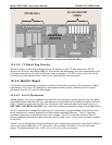
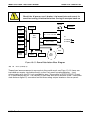
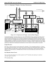
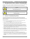
Figure 10-18: Keyboard and Display Interface Block Diagram
The keyboard/display interface electronics of the MGFC7000E Analyzer watches the status of the
eight front panel keys, alerts the CPU when keys are depressed, translates data from parallel to
serial and back and manages communications between the keyboard, the CPU and the front panel
display. Except for the Keyboard interrupt status bit, all communication between the CPU and the
keyboard/display is handle by way of the instrument’s I
2
C buss. The CPU controls the clock signal
and determines when the various devices on the bus are allowed to talk or required to listen. Data
packets are labeled with addresses that identify for which device the information is intended.
Keypad Decoder
Each key on the front panel communicates with a decoder IC via a separate analog line. When a
key is depressed the decoder chip notices the change of state of the associated signal; latches and
holds the state of all eight lines (in effect creating an 8-bit data word); alerts the key-depress-
detect circuit (a flip-flop IC); translates the 8-bit word into serial data and; sends this to the I
2
C
interface chip.
Key-Depress-Detect Circuit
This circuit flips the state of one of the inputs to the I
2
C interface chip causing it to send an
interrupt signal to the CPU
I
2
C Interface Chip