


Model GFC7000E Instruction Manual Calibration Procedures
04584 Rev A1 131
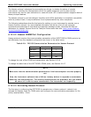
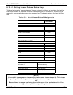
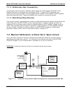
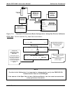
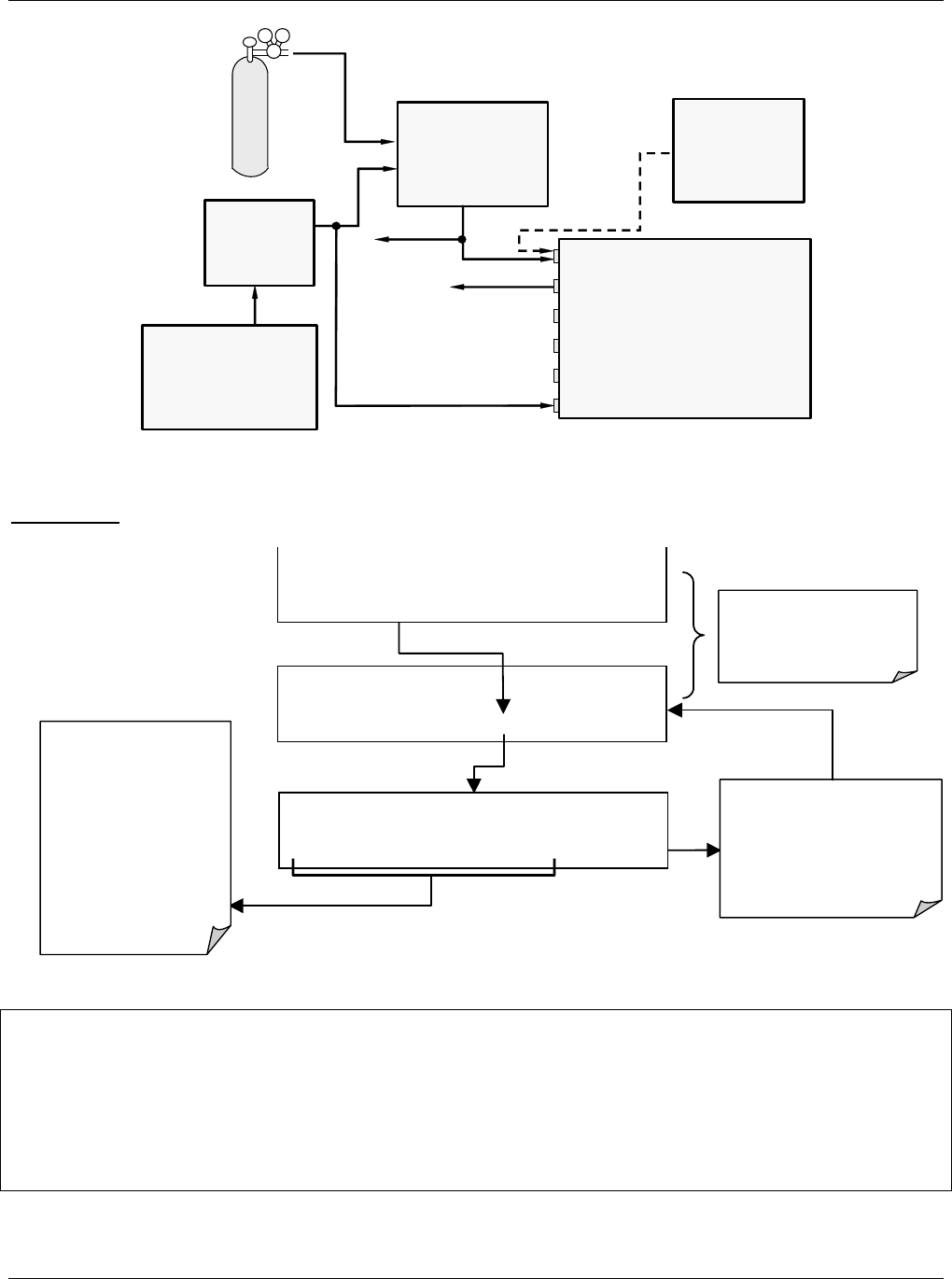
MODEL 700
Gas Dilution
Calibrator
VENT
Calibrated
CO
2
Gas
Source of
SAMPLE Gas
Removed
during
Calibration
MODEL
GFC7000E
Sam
p
le
IZS
Exhaust
Vent S
p
an
Pressure Span
Pur
g
e In
MODEL 701
Zero Air Generator
Indicating
soda-lime
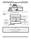
Figure 7-2: Pneumatic Connections–Basic Configuration–Using Gas Dilution Calibrator
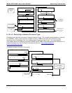
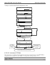
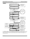
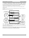
STEP TWO
: Set the expected CO
2
Span Gas concentration:
This sequence causes the
analyzer to prompt for the
expected CO
x
span
concentration.
M-P CAL
SO2 SPAN CONC: 400.000 Conc
0 0 0 4 5 .0 ENTR EXIT
M-P CAL RANGE = 500.000 PPM CO2 =X.XXX
< TST TST > ZERO
CONC
EXIT
SAMPLE* RANGE = 500.000 PPM CO2 =X.XXX
< TST TST >
CAL
SETUP
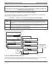
The SO
2
span
concentration values
automatically default to
400.0 Conc.
To change this value to
the actual concentration of
the span gas, enter the
number by pressing the
key under each digit until
the expected value
appears.
EXIT ignores the new setting
and returns to the previous
display.
ENTR accepts the new setting
and returns to the
previous display..
NOTE
For this Initial Calibration it is important to independently verify the PRECISE CO
2
Concentration Value of the SPAN gas.
If the source of the Span Gas is from a Calibrated Bottle, use the exact concentration
value printed on the bottle.