


3 - 40
3. SIGNALS AND WIRING
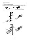
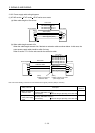
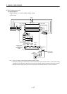
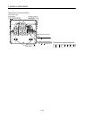
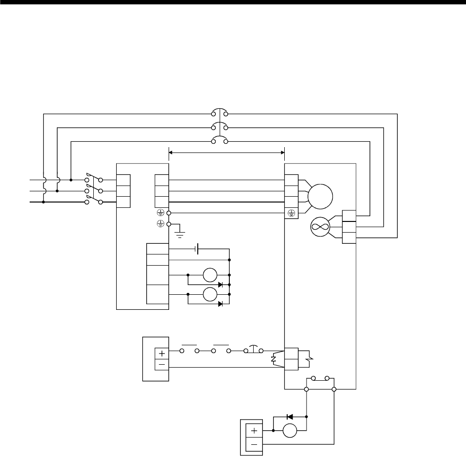
(3) HA-LP series servo motor
(a) Wiring diagrams
Refer to section 11.11 for the cables used for wiring.
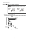
1) 200V class
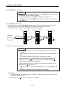
Servo motor
(Note 1)
Servo amplifier
U
V
W
B1
B2
U
V
W
24VDC power
supply for
electromagnetic
brake
50m or less
Forced
stop
(EM1)
Trouble
(ALM)
RA1
24VDC
ALM
DOCOM
DICOM
MBR
CN3
RA1
RA2
Electromagnetic
brake interlock
(MBR)
RA2
RA3
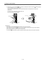
M
Cooling fan
(Note 2)
24VDC
power supply
OHS2OHS1 Servo motor
thermal relay
(Note 3)
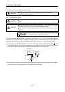
L
1
L2
L
3
BU
BV
BW
TE
MC
NFB
Note 1. There is no polarity in electromagnetic brake terminals B1 and B2.
2. Cooling fan power supply of the HA-LP601, the HA-LP701M and the HA-LP11K2 servo motor is 1-phase. Power supply
specification of the cooling fan is different from that of the servo amplifier. Therefore, separate power supply is required.
3. Configure the power supply circuit which turns off the magnetic contactor after detection of servo motor thermal.