


3
6.4 Interpolation mode ..................................................................................................................................6 -11
6.5 Differences between MELSERVO-J2-Super and MELSERVO-J3 in auto tuning................................6 -12
7. SPECIAL ADJUSTMENT FUNCTIONS 7 - 1 to 7 -16
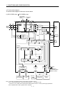
7.1 Function block diagram............................................................................................................................7 - 1
7.2 Adaptive filter
.........................................................................................................................................7 - 1
7.3 Machine resonance suppression filter..................................................................................................... 7 - 4
7.4 Advanced vibration suppression control .................................................................................................7 - 6
7.5 Low-pass filter .........................................................................................................................................7 -10
7.6 Gain changing function ...........................................................................................................................7 -10
7.6.1 Applications ......................................................................................................................................7 -10
7.6.2 Function block diagram....................................................................................................................7 -11
7.6.3 Parameters.......................................................................................................................................7 -12
7.6.4 Gain changing operation..................................................................................................................7 -14
8. TROUBLESHOOTING 8 - 1 to 8 -10
8.1 Alarms and warning list............................................................................................................................ 8 - 1
8.2 Remedies for alarms................................................................................................................................ 8 - 2
8.3 Remedies for warnings ............................................................................................................................ 8 - 8
9. OUTLINE DRAWINGS 9 - 1 to 9 -12
9.1 Servo amplifier .........................................................................................................................................9 - 1
9.2 Connector................................................................................................................................................9 -10
10. CHARACTERISTICS 10- 1 to 10-10
10.1 Overload protection characteristics......................................................................................................10- 1
10.2 Power supply equipment capacity and generated loss .......................................................................10- 3
10.3 Dynamic brake characteristics..............................................................................................................10- 6
10.3.1 Dynamic brake operation...............................................................................................................10- 6
10.3.2 The dynamic brake at the load inertia moment............................................................................. 10- 9
10.4 Cable flexing life...................................................................................................................................10-10
10.5 Inrush currents at power-on of main circuit and control circuit...........................................................10-10
11. OPTIONS AND AUXILIARY EQUIPMENT 11- 1 to 11-90
11.1 Cable/connector sets ............................................................................................................................11- 1
11.1.1 Combinations of cable/connector sets ..........................................................................................11- 2
11.1.2 Encoder cable/connector sets .......................................................................................................11- 8
11.1.3 Motor power supply cables...........................................................................................................11-17
11.1.4 Motor brake cables........................................................................................................................11-18
11.1.5 SSCNET
cable ...........................................................................................................................11-19
11.2 Regenerative options...........................................................................................................................11-21
11.3 FR-BU2-(H) Brake unit.........................................................................................................................11-34
11.3.1 Selection........................................................................................................................................11-35
11.3.2 Brake unit parameter setting.........................................................................................................11-35
11.3.3 Connection example .....................................................................................................................11-36