


3 - 46
3. SIGNALS AND WIRING
3.11 Servo motor with an electromagnetic brake
3.11.1 Safety precautions
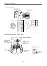
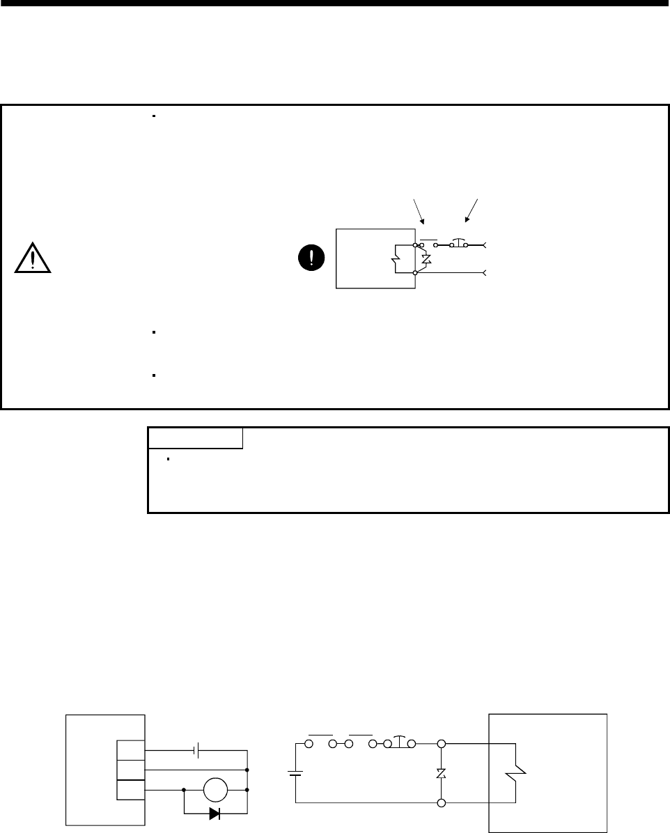
CAUTION
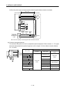
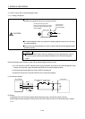
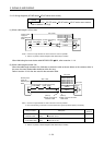
Configure the electromagnetic brake circuit so that it is activated not only by the
interface unit signals but also by a forced stop (EM1).
EM1RA
24VDC
Contacts must be open when
servo-off, when an alarm occurrence
and when an electromagnetic brake
interlock (MBR).
Electroma
g
netic brake
Servo motor
Circuit must be
opened during
forced stop (EM1).
The electromagnetic brake is provided for holding purpose and must not be used
for ordinary braking.
Before performing the operation, be sure to confirm that the electromagnetic brake
operates properly.
POINT
Refer to the Servo Motor Instruction Manual (Vol.2) for specifications such as
the power supply capacity and operation delay time of the electromagnetic
brake.
Note the following when the servo motor with an electromagnetic brake is used.
1) Do not share the 24VDC interface power supply between the interface and electromagnetic brake.
Always use the power supply designed exclusively for the electromagnetic brake.
2) The brake will operate when the power (24VDC) switches off.
3) Switch off the servo-on command after the servo motor has stopped.
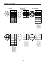
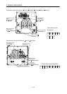
(1) Connection diagram
Servo amplifier
Servo motor
B1
B2
Forced
stop
24VDC
Electromagnetic
brake
Trouble
(ALM)
DICOM
MBR RA1
DOCOM
24VDC
(2) Setting
In parameter No.PC02 (electromagnetic brake sequence output), set the time delay (Tb) from
electromagnetic brake operation to base circuit shut-off at a servo off time as in the timing chart in section
3.11.2.