


4
11.3.4 Outline dimension drawings..........................................................................................................11-43
11.4 Power regeneration converter .............................................................................................................11-45
11.5 Power regeneration common converter..............................................................................................11-48
11.6 External dynamic brake .......................................................................................................................11-56
11.7 Junction terminal block PS7DW-20V14B-F (recommended).............................................................11-61
11.8 MR Configurator...................................................................................................................................11-62
11.9 Battery MR-J3BAT ...............................................................................................................................11-64
11.10 Heat sink outside mounting attachment (MR-J3ACN)......................................................................11-65
11.11 Selection example of wires................................................................................................................11-67
11.12 No-fuse breakers, fuses, magnetic contactors .................................................................................11-72
11.13 Power factor improving DC reactor ...................................................................................................11-72
11.14 Power factor improving AC reactors .................................................................................................11-74
11.15 Relays (recommended) .....................................................................................................................11-75
11.16 Surge absorbers (recommended) .....................................................................................................11-76
11.17 Noise reduction techniques ...............................................................................................................11-76
11.18 Leakage current breaker....................................................................................................................11-83
11.19 EMC filter (recommended) ................................................................................................................11-85
12. ABSOLUTE POSITION DETECTION SYSTEM 12- 1 to 12- 6
12.1 Features ................................................................................................................................................12- 1
12.2 Specifications ........................................................................................................................................12- 2
12.3 Battery installation procedure ...............................................................................................................12- 3
12.4 Confirmation of absolute position detection data.................................................................................12- 5
13. SERVO AMPLIFIERS WITH A LARGE CAPACITY (30k TO 55kW) 13- 1 to 13-102
13.1. Functions and menus...........................................................................................................................13- 1
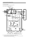
13.1.1 Function block diagram..................................................................................................................13- 2
13.1.2 Packing list .....................................................................................................................................13- 4
13.1.3 Standard specifications..................................................................................................................13- 5
13.1.4 Model definition ..............................................................................................................................13- 8
13.1.5 Combinations of converter units, drive unit and servo motors .....................................................13- 9
13.1.6 Parts identification.........................................................................................................................13-10
13.1.7 Removal and reinstallation of the terminal block cover ...............................................................13-13
13.1.8 Servo system with auxiliary equipment ........................................................................................13-19
13.2 Installation ............................................................................................................................................13-20
13.2.1 Installation direction and clearances ............................................................................................13-21
13.2.2 Inspection ......................................................................................................................................13-22
13.3 Signals and wiring................................................................................................................................13-23
13.3.1 Magnetic contactor control connector (CNP1).............................................................................13-24
13.3.2 Input power supply circuit .............................................................................................................13-26
13.3.3 Terminal.........................................................................................................................................13-31
13.3.4 How to use the connection bars ...................................................................................................13-32
13.3.5 Connectors and signal arrangements ..........................................................................................13-33
13.3.6 Converter unit signal (device) explanations .................................................................................13-35
13.3.7 Timing chart...................................................................................................................................13-37
13.3.8 Servo motor side details ...............................................................................................................13-47
13.4 Display section and operation section of the converter unit...............................................................13-49