


4 - 5
4. STARTUP
4.3 Servo amplifier display
On the servo amplifier display (three-digit, seven-segment display), check the status of communication with the
servo system controller at power-on, check the axis number, and diagnose a fault at occurrence of an alarm.
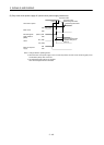
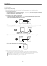
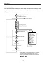
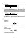
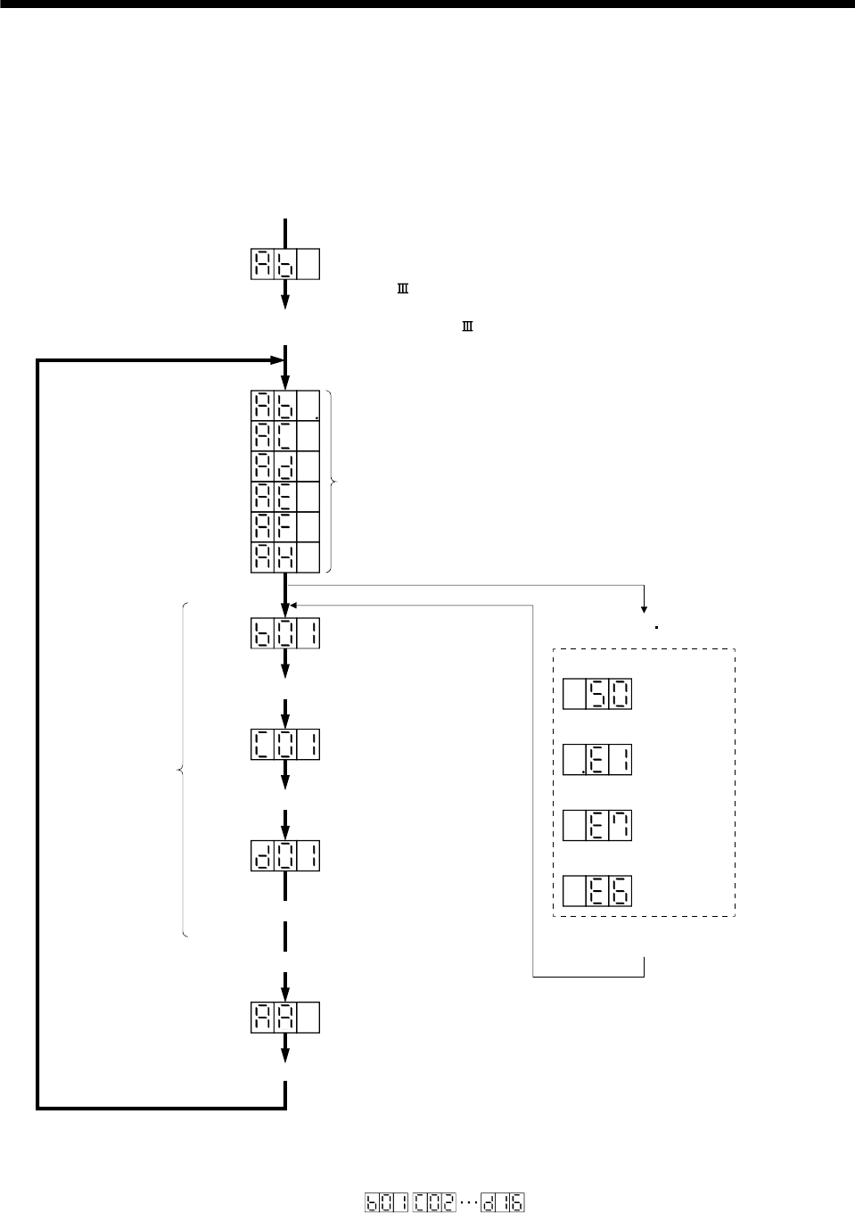
(1) Display sequence
Only alarm and warning No. are displayed, but no axis No. is displayed
Servo amplifier power ON
(Note 3)
At occurrence of overload
At occurrence of overload
warning (Note 2)
During controller
forced stop
During forced stop
Flicker
display
Alarm reset or
warning
1 axis 2 axis 16 axis
(Note 3)
(Note 3)
(Note 1)
When alarm warning
No. is displayed
Flicker
display
Flicker
display
Flicker
display
If warning other than E6 or E7 occurs during the servo on, flickering the
second place of decimal point indicates that it is during the servo on.
Note 1.
2.
3.
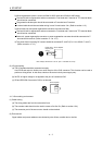
The right-hand segments of b01, c02 and d16 indicate the axis number.
(Below example indicates Axis1)
Initial data communication
with servo system controller
(Initialization communication)
When alarm occurs,
alarm code appears.
Ready ON
Ready OFF/servo OFF
Ready ON/servo OFF
Servo ON
Ready ON/servo ON
Servo system controller power ON
Ordinary operation
Servo system controller power OFF
Waiting for servo system controller
power to switch ON
(SSCNET communication)
Servo system controller power ON (SSCNET communication beginning)