


13 - 21
13. SERVO AMPLIFIERS WITH A LARGE CAPACITY (30k TO 55kW)
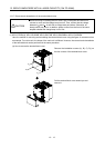
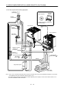
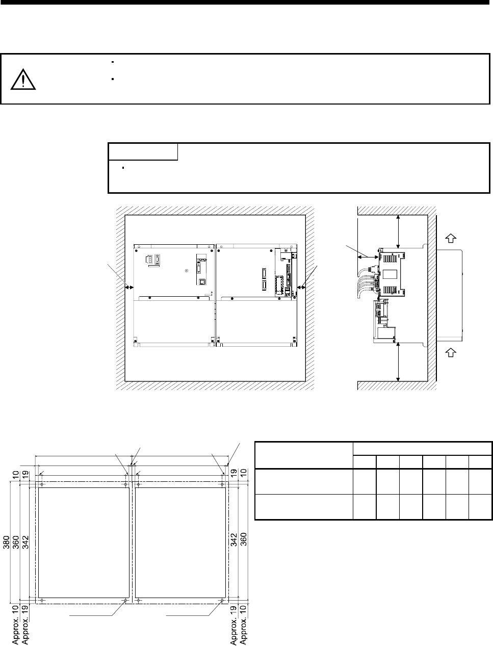
13.2.1 Installation direction and clearances
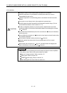
CAUTION
Install the equipment in the specified direction. Not doing so can cause a failure.
Leave the specified clearances between the converter unit/drive unit and the
control box inside walls or other equipment. Not doing so can cause a failure.
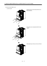
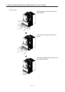
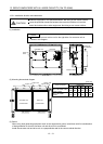
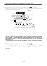
(1) Installation
POINT
Make sure to connect a drive unit to the right side of a converter unit as
shown in the diagram.
80mm or
more
Side view
Drive unitConverter unit
Front view
100mm or
more
120mm or more
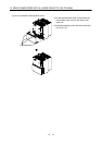
30mm or
more
30mm or
more
Cooling fan
wind direction
Air
intake
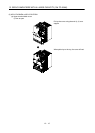
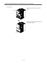
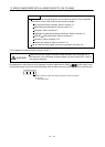
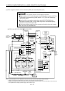
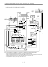
(2) Mounting dimensional diagram
[Unit: mm]
Dimensions
Drive unit model
W1 W2 W3 W4 W5 A
MR-J3-DU30KB, 37KB,
45KB4, 55KB4
300 260 20 281 9.5 M6
MR-J3-DU30KB4,
37KB4
240 120 60 222 9 M5
9.5
Converter unit
punched hole
Drive unit
punched hole
4-M6 screw
300
20
260
281
Approx. 9.5
Approx. 20
4-M6 screw
W1
W3
W2
W4
Approx. W5
Approx. W3
W5
(3) Others
When using heat generating equipment such as the regenerative option, install them with full consideration
of heat generation so that the converter unit and drive unit is not affected.
Install the converter unit and drive unit on a perpendicular wall in the correct vertical direction.