


5 - 26
5. PARAMETERS
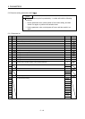
5.4.2 List of details
No. Symbol Name and function
Initial
value
Unit
Setting
range
PD01 0000h
PD02
For manufacturer setting
Do not change this value by any means.
0000h
PD03 0000h
PD04 0000h
PD05 0000h
PD06
0000h
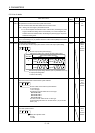
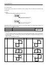
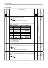
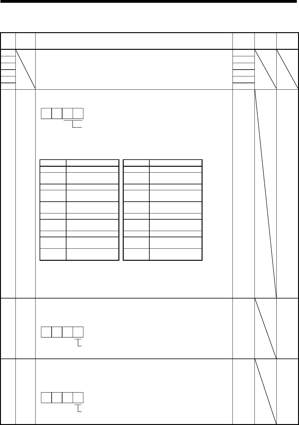
PD07 *DO1 Output signal device selection 1 (CN3-13)
Any input signal can be assigned to the CN3-13 pin.
Select the output device of the CN3-13 pin.
00
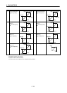
The devices that can be assigned in each control mode are those that have the symbols
indicated in the following table.
0005h Refer to
Name
and
function
column.
Setting Device Setting Device
00 Always OFF 0A Always OFF (Note 2)
01
For manufacturer
setting (Note 3)
0B
For manufacturer
setting (Note 3)
02 RD 0C ZSP
03 ALM 0D
For manufacturer
setting (Note 3)
04 INP (Note 1) 0E
For manufacturer
setting (Note 3)
05 MBR 0F CDPS
06 DB 10
For manufacturer
setting (Note 3)
07 TLC 11 ABSV (Note 1)
08 WNG 12 to 1F
For manufacturer
setting (Note 3)
09 BWNG 20 to 3F
For manufacturer
setting (Note 3)
Note 1. It becomes always OFF in speed control mode.
2. It becomes SA in speed control mode.
3. For manufacturer setting
Never change this setting.
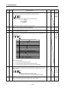
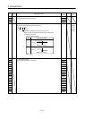
PD08 *DO2
Output signal device selection 2 (CN3-9)
Any input signal can be assigned to the CN3-9 pin.
The devices that can be assigned and the setting method are the same as in parameter
No.PD07.
Select the output device of the CN3-9 pin.
000
0004h Refer to
Name
and
function
column.
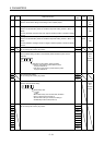
PD09 *DO3 Output signal device selection 3 (CN3-15)
Any input signal can be assigned to the CN3-15 pin.
The devices that can be assigned and the setting method are the same as in parameter
No.PD07.
Select the output device of the CN3-15 pin.
000
0003h Refer to
Name
and
function
column.